EasyManua.ls Logo

Mitsubishi Electric PUH-P2VGA - User Manual

Mitsubishi Electric PUH-P2VGA
44 pages
Print Icon
To Next Page IconTo Next Page
Loading...
TECHNICAL & SERVICE MANUAL
SPLIT-TYPE, HEAT PUMP AIR CONDITIONERS
CONTENTS
1. SAFETY PRECAUTION··································3
2.
COMBINATION OF INDOOR AND OUTDOOR UNITS
···5
3. PART NAMES AND FUNCTIONS ··················5
4. SPECIFICATIONS···········································6
5. DATA ·····························································12
6. OUTLINES AND DIMENSIONS····················15
7. WIRING DIAGRAM·······································19
8.
REFRIGERANT SYSTEM DIAGRAM
·············23
9. DISASSEMBLY PROCEDURE·····················25
10. PARTS LIST ··················································29
11. OPTIONAL PARTS ························Back cover
Outdoor unit
[model names]
PUH-P1.6VGA PU-P1.6VGA
PUH-P1.6YGA
PUH-P2VGA PU-P2VGA
PUH-P2YGA
PUH-P2.5VGA PU-P2.5VGA
PUH-P2.5YGA
PUH-P3VGA PU-P3VGA
PUH-P3YGA PU-P3YGA
PUH-P4YGA PU-P4YGA
PUH-P5YGA PU-P5YGA
PUH-P6YGA PU-P6YGA
No.OC180
REVISED EDITION-A
1999
R407C
[Service Ref.]
PUH-P1.6VGA PU-P1.6VGA
PUH-P1.6YGA
PUH-P2VGA PU-P2VGA
PUH-P2YGA
PUH-P2.5VGA PU-P2.5VGA
PUH-P2.5VGA
1 PU-P2.5VGA1
PUH-P2.5YGA
PUH-P2.5YGA
1
PUH-P3VGA PU-P3VGA
PUH-P3YGA PU-P3YGA
PUH-P4YGA PU-P4YGA
PUH-P5YGA PU-P5YGA
PUH-P6YGA PU-P6YGA
Revision:
PUH-P1.6YGA, -P2YGA, -P2.5YGA,
PUH-P2.5VGA1, -P2.5YGA1 and
PU-P1.6VGA, -P2VGA, -P2.5VGA,
PU-P3VGA, -P3YGA, -P4YGA, -P5YGA,
PU-P6YGA, -P2.5VGA1 added in
Revised Edition-A.
Please destroy OC180.
OC180A--1.qxp 3/3/00 8:43 AM Page 1
Question and Answer IconNeed help?

Do you have a question about the Mitsubishi Electric PUH-P2VGA and is the answer not in the manual?

Summary

SAFETY PRECAUTION

COMBINATION OF INDOOR AND OUTDOOR UNITS

PART NAMES AND FUNCTIONS

SPECIFICATIONS

1. Heat pump

Specifications for heat pump units, detailing performance and dimensions.

2. Cooling only type

Specifications for cooling-only units, detailing performance and dimensions.

DATA

1. REFILLING REFRIGERANT CHARGE

Details on refrigerant charge amounts based on piping length.

2. COMPRESSOR TECHNICAL DATA

Technical specifications for compressor winding resistance.

OUTLINES AND DIMENSIONS

1 FREE SPACE (Around the Unit)

Required clearance around the unit for installation and operation.

2 SERVICE SPACE

Space needed for maintenance and servicing access.

3 FOUNDATION BOLTS

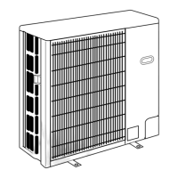
Instructions for securing the unit with foundation bolts.

4 PIPING-WIRING DIRECTIONS

Guidance on connection directions for piping and wiring.

WIRING DIAGRAM

REFRIGERANT SYSTEM DIAGRAM

DISASSEMBLY PROCEDURE

1. Removing the Service panel and Top panel

Steps to remove the service and top panels for access.

2. Removing the Fan and Fan motor

Procedure for removing the fan and motor components.

3. Removing the Electrical box

Instructions for removing the electrical box and its cover.

5. Removing the bypass valve solenoid coil (SV)

Procedure to remove the bypass valve solenoid coil.

6. Removing the bypass valve

Steps for removing the bypass valve.

7. Removing the R.V. coil (21 S4)

Procedure to remove the R.V. coil.

8. Removing the 4-way valve

Procedure to remove the 4-way valve.

9. Removing the pressure switch

Procedures for removing low and high pressure switches.

10. Removing the refrigerant capillary tube

Steps to remove the refrigerant capillary tube.

11. Removing the Bell mouth

Procedure for removing the bell mouth component.

12. Removing the compressor

Detailed steps for removing the compressor from the unit.

13. Removing the accumulator.

Procedure to remove the accumulator.

PARTS LIST

OPTIONAL PARTS

Mitsubishi Electric PUH-P2VGA Specifications

General IconGeneral
CategoryAir Conditioner
ModelPUH-P2VGA
Cooling Capacity2.5 kW
Heating Capacity3.2 kW
Weight (Indoor Unit)9 kg
Power Supply220-240 V, 50 Hz
Outdoor Unit Dimensions (W x H x D)780 x 540 mm

Related product manuals