EasyManua.ls Logo

Mitsubishi Electric PUHZ-SW75VAA-SC User Manual

Mitsubishi Electric PUHZ-SW75VAA-SC
78 pages
To Next Page IconTo Next Page
Page #1 background imageLoading...
Page #1 background image
SERVICE MANUAL
No. OCH651
REVISED EDITION-A
R410A
August 2017
Revision:
Added
PUHZ-SW75VAA-SC.UK and
PUHZ-SW75YAA-SC.UK
in REVISED EDITION-A.
Some descriptions have
been modified.
PARTS CATALOG (OCB651)
[Model Name]
PUHZ-SHW80VAA
PUHZ-SHW112VAA
PUHZ-SHW80YAA
PUHZ-SHW112YAA
PUHZ-SW75VAA
PUHZ-SW100VAA
PUHZ-SW75YAA
PUHZ-SW100YAA
PUHZ-SW75VAA-SC
PUHZ-SW75YAA-SC
Salt proof model
PUHZ-SHW80VAA-BS
PUHZ-SHW112VAA-BS
PUHZ-SHW80YAA-BS
PUHZ-SHW112YAA-BS
PUHZ-SW75VAA-BS
PUHZ-SW100VAA-BS
PUHZ-SW75YAA-BS
PUHZ-SW100YAA-BS
CONTENTS
1. REFERENCE MANUAL ································ 2
2. SAFETY PRECAUTION ······························· 3
3. SPECIFICATIONS ········································ 7
4. DATA ··························································· 10
5. OUTLINES AND DIMENSIONS·················· 12
6. WIRING DIAGRAM ····································· 13
7. WIRING SPECIFICATIONS ························ 17
8. REFRIGERANT SYSTEM DIAGRAM ········ 18
9. TROUBLESHOOTING ································ 21
10.
MONITORING THE OPERATION DATA BY THE REMOTE CONTROLLER
···· 60
11. DISASSEMBLY PROCEDURE ··················· 66
Note:
• This manual describes
service data of the outdoor
units only.
OCH651 is void.
AIR TO WATER HEAT PUMP UNITS
[Service Ref.]
PUHZ-SHW80VAA.UK
PUHZ-SHW112VAA.UK
PUHZ-SHW80YAA.UK
PUHZ-SHW112YAA.UK
PUHZ-SW75VAA.UK
PUHZ-SW100VAA.UK
PUHZ-SW75YAA.UK
PUHZ-SW100YAA.UK
PUHZ-SW75VAA-SC.UK
PUHZ-SW75YAA-SC.UK
PUHZ-SHW80VAA-BS.UK
PUHZ-SHW112VAA-BS.UK
PUHZ-SHW80YAA-BS.UK
PUHZ-SHW112YAA-BS.UK
PUHZ-SW75VAA-BS.UK
PUHZ-SW100VAA-BS.UK
PUHZ-SW75YAA-BS.UK
PUHZ-SW100YAA-BS.UK
Question and Answer IconNeed help?

Do you have a question about the Mitsubishi Electric PUHZ-SW75VAA-SC and is the answer not in the manual?

Mitsubishi Electric PUHZ-SW75VAA-SC Specifications

General IconGeneral
BrandMitsubishi Electric
ModelPUHZ-SW75VAA-SC
CategoryHeat Pump
LanguageEnglish

Summary

Reference Manual: Indoor Unit Details

Indoor Unit Service Manual 1-1. For Air to Water System

Details about indoor units for air to water systems, listing models and service manual numbers.

Safety Precautions and Guidelines

General Safety Observance

General safety guidelines to follow before and during repair service.

R410A Refrigerant Handling Cautions

Specific precautions for R410A refrigerant, including tools and procedures.

Reusing Existing R22 Refrigerant Pipes

Flowchart and precautions for reusing existing R22 refrigerant pipes.

Salt Proof Model "-BS" Precautions

Specific precautions for salt-proof models to maintain performance and prevent damage.

Outdoor Unit Specifications

Technical Data and Performance

Refrigerant Charge and Compressor Data

Data on refrigerant charge amounts and compressor technical details for various models.

Noise Criterion Curves

Octave band sound pressure levels for different models in cooling and heating modes.

Physical Specifications and Dimensions

Wiring Diagrams and Specifications

Field Electrical Wiring Specifications

Details on wire sizing, circuit ratings, and connection notes for field wiring.

Refrigerant System and Troubleshooting Overview

Refrigerant System Diagrams

Diagrams illustrating the refrigerant flow in cooling and heating modes for various models.

Troubleshooting Guide Overview

General troubleshooting approach based on self-diagnosis codes and reoccurring issues.

Self-Diagnosis and Error Code Analysis

Power On Self-Diagnosis Abnormalities

Details abnormalities detected when power is on and their corresponding actions.

Troubleshooting Common Phenomena

Troubleshooting guide for common phenomena like remote controller issues and capacity problems.

Component Testing and Diagnostics

Component Resistance and Feature Checks

Instructions for measuring resistance of various components like thermistors, motors, and valves.

Component Inspection Methods and Diagrams

Methods for checking components like DC fan motor, power supply, and high pressure sensor.

Test Point Diagrams for Circuit Boards

Diagrams showing test points on the outdoor controller circuit board for diagnosis.

Switches, Connectors, and Jumpers Functionality

Outdoor Unit Inspection Display and Monitoring

Error Postponement and Blinking Display Interpretation

Details on how error postponement codes and blinking patterns indicate unit status.

SW2 Settings for Diagnostic Display

Explanation of SW2 settings used for displaying diagnostic information and unit status.

Remote Controller Operation Data Monitoring

Request Codes for Operation Data Monitoring

List of request codes and their corresponding data descriptions for monitoring operations.
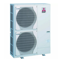
Disassembly and Reassembly Procedures

Related product manuals