SERVICE MANUAL
CONTENTS
1. TECHNICAL CHANGES
..................................
3
2. SAFETY PRECAUTION
...................................
5
3. SPECIFICATIONS
............................................
8
4. DATA
.............................................................
31
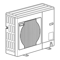
5. OUTLINES AND DIMENSIONS
.....................
34
6. WIRING DIAGRAM
........................................
37
7. WIRING SPECIFICATIONS
...........................
49
8. REFRIGERANT SYSTEM DIAGRAM
...............
50
9. TROUBLESHOOTING
...................................
52
10. DISASSEMBLY PROCEDURE
....................
103
Notes:
• This manual describes service
data of outdoor unit only.
R410A
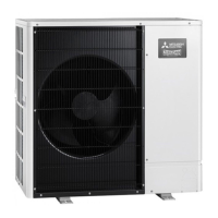
[Model Name]
PUHZ-W50VHA
PUHZ-W85VHA
PUHZ-HW112YHA
PUHZ-HW112YHA2
PUHZ-HW140VHA
PUHZ-HW140YHA
PUHZ-HW140VHA2
PUHZ-HW140YHA2
PUHZ-W85VHA(R1)
PUHZ-W85VHA(R1)-BS
PARTS CATALOG (OCB439)
• OCH439 REVISED EDITION-L
is void.
PUHZ-W50VHA-BS
PUHZ-W85VHA-BS
PUHZ-HW112YHA-BS
PUHZ-HW112YHA2-BS
PUHZ-HW140VHA-BS
PUHZ-HW140YHA-BS
PUHZ-HW140VHA2-BS
PUHZ-HW140YHA2-BS
[Service Ref.]
Refer to page 2.
SPLIT-TYPE, AIR TO WATER HEAT PUMP
No. OCH439
REVISED EDITION-M
April 2019
Revision:
• Added
PUHZ-HW112YHA2R7,
PUHZ-HW112YHA2R7-BS,
PUHZ-HW140VHA2R7,
PUHZ-HW140VHA2R7-BS,
PUHZ-HW140YHA2R7 and
PUHZ-HW140YHA2R7-BS in
REVISED EDITION-M.
• Some descriptions have been
modified.