EasyManua.ls Logo

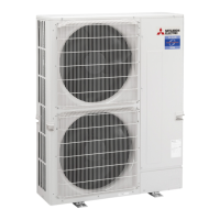
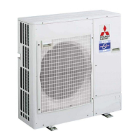
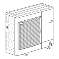
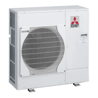
Mitsubishi Electric PUHZ-ZRP100YKA3 User Manual

Mitsubishi Electric PUHZ-ZRP100YKA3
119 pages
To Next Page IconTo Next Page
Page #1 background imageLoading...
Page #1 background image
SPLIT-TYPE, HEAT PUMP AIR CONDITIONERS
SERVICE MANUAL
R410A
Outdoor unit
[Model Name]
PUHZ-ZRP100VKA3
PUHZ-ZRP125VKA3
PUHZ-ZRP140VKA3
PUHZ-ZRP100YKA3
PUHZ-ZRP125YKA3
PUHZ-ZRP140YKA3
PUHZ-ZRP200YKA2
PUHZ-ZRP250YKA2
[Service Ref.]
PUHZ-ZRP100VKA3.UK
PUHZ-ZRP125VKA3.UK
PUHZ-ZRP140VKA3.UK
PUHZ-ZRP100YKA3.UK
PUHZ-ZRP125YKA3.UK
PUHZ-ZRP140YKA3.UK
PUHZ-ZRP200YKA2.UK
PUHZ-ZRP250YKA2.UK
PARTS CATALOG (OCB645)
CONTENTS
1. REFERENCE MANUAL ································· 2
2. SAFETY PRECAUTION ································· 2
3. FEATURES ····················································· 6
4. SPECIFICATIONS ·········································· 7
5. DATA ······························································· 9
6. OUTLINES AND DIMENSIONS ··················· 13
7. WIRING DIAGRAM ······································ 15
8. WIRING SPECIFICATIONS ·························· 18
9.
REFRIGERANT SYSTEM DIAGRAM
············· 23
10. TROUBLESHOOTING ·································· 26
11. FUNCTION SETTING ··································· 83
12.
MONITORING THE OPERATION DATA BY THE REMOTE CONTROLLER
···· 92
13. EASY MAINTENANCE FUNCTION ··········· 101
14. DISASSEMBLY PROCEDURE ··················· 104
Note:
•
This manual describes service
data of the outdoor units only.
No. OCH645
September 2016

Other manuals for Mitsubishi Electric PUHZ-ZRP100YKA3

Questions and Answers:

Mitsubishi Electric PUHZ-ZRP100YKA3 Specifications

General IconGeneral
BrandMitsubishi Electric
ModelPUHZ-ZRP100YKA3
CategoryAir Conditioner
LanguageEnglish

Summary

REFERENCE MANUAL

SAFETY PRECAUTION

Safety rules before accessing terminals. Cautions for units utilizing R410A refrigerant. Guidelines for reusing R22 refrigerant pipes.

Service tools

Tools for R410A

Table detailing tools specific to R410A refrigerant and their compatibility.

FEATURES

CHARGELESS SYSTEM

Pre-charged refrigerant system for piping length at shipment, simplifying installation.

SPECIFICATIONS

DATA

REFILLING REFRIGERANT CHARGE (R410A: kg)

Refilling refrigerant charge amounts for R410A models based on piping length.

ADJUSTING REFRIGERANT AMOUNT PUHZ-ZRP200/250

Procedure for adjusting refrigerant amount for specific models.

COMPRESSOR TECHNICAL DATA

Technical specifications and data for compressors.

NOISE CRITERION CURVES

Noise levels measured across frequency bands for different models.

STANDARD OPERATION DATA

Standard operational parameters for various model combinations.

OUTLINES AND DIMENSIONS

WIRING DIAGRAM

WIRING SPECIFICATIONS

FIELD ELECTRICAL WIRING (power wiring specifications)

Specifications for field electrical wiring and power supply connections.

SEPARATE INDOOR/OUTDOOR UNIT POWER SUPPLIES

Connection patterns for separate power supply configurations.

INDOOR – OUTDOOR CONNECTING CABLE

Cable specifications and connection guidelines for indoor/outdoor units.

M-NET WIRING METHOD

Guidelines and precautions for M-NET communication wiring.

REFRIGERANT SYSTEM DIAGRAM

REFRIGERANT COLLECTING (PUMP DOWN)

Procedure for collecting refrigerant before unit removal or disposal.

START AND FINISH OF TEST RUN

Steps for performing and concluding a test run of the unit.

TROUBLESHOOTING

TROUBLESHOOTING SUMMARY

Overview of troubleshooting based on unit conditions and check codes.

CHECK POINT UNDER TEST RUN

Points to check before and during unit test runs.

M-NET communication error troubleshooting

Steps to resolve M-NET communication errors.

Remote Controller Operation Issues

Troubleshooting common problems related to remote controller operation.

HOW TO PROCEED "SELF-DIAGNOSIS"

Self-diagnosis <PAR-3xMAA>

Procedure for performing self-diagnosis using wired remote controller.

Remote controller check <PAR-3xMAA>

Procedure for checking remote controller communication and function.

Self-diagnosis for wireless remote controller (Type C)

Self-diagnosis procedure for wireless remote controller (Type C).

Self-diagnosis for wireless remote controller (PAR-SL100A-E)

Self-diagnosis procedure for wireless remote controller (PAR-SL100A-E).

SELF-DIAGNOSIS ACTION TABLE

Abnormalities detected when the power is put on

Actions for diagnosing abnormalities found upon initial power-up.

Abnormalities detected while unit is operating

Actions for diagnosing abnormalities occurring during unit operation.

HOW TO CHECK THE PARTS

DC Fan Motor and Circuit Board Check

Procedure for checking the DC fan motor and associated circuit boards.

Component Checking: Thermistor Feature Chart

Resistance values for various thermistors at different temperatures.

Linear Expansion Valve Operation and Connection

Details on LEV operation, signals, and wiring connections.

EMERGENCY OPERATION

Conditions and Cautions for Emergency Operation

Parameters and safety considerations for emergency operation.

Emergency Operation Procedure

Step-by-step guide to performing emergency operation.

Releasing Emergency Operation

Steps to correctly exit the emergency operation mode.

Operation Data During Emergency Operation

Specific data values used during emergency operation.

TEST POINT DIAGRAM

FUNCTION OF SWITCHES, CONNECTORS AND JUMPERS

Function of Switches

Explanation of DIP and push switch functions and their operations.

Function of Connectors

Explanation of various connector functions on the circuit boards.

Special Functions

Details on special functions like low-level sound priority and demand control.

FUNCTION SELECTION OF REMOTE CONTROLLER

Remote Controller Function Buttons <PAR-32MAA>

Explanation of the functions of buttons on the remote controller.

Remote Controller Menu Structure

Navigation flow and options within the remote controller menu.

Main Menu List: Setting and Display Items

Detailed descriptions of main menu items and their settings.

MONITORING OPERATION DATA BY REMOTE CONTROLLER

HOW TO "MONITOR THE OPERATION DATA"

How to monitor operation data using the remote controller.

Request Code List for Operation Data

Comprehensive list of request codes for accessing operation data.

EASY MAINTENANCE FUNCTION

SMOOTH MAINTENANCE

Overview and procedure for the smooth maintenance function.

Guide for Operation Condition Judgment

Using graphs to judge operation conditions based on temperature differences.

DISASSEMBLY PROCEDURE

Related product manuals