TECHNICAL & SERVICE MANUAL
SPLIT-TYPE, HEAT PUMP AIR CONDITIONERS
CONTENTS
1. TECHNICAL CHANGE
......................................
2
2. SAFETY PRECAUTION
....................................
3
3. OVERVIEW OF UNITS
......................................
6
4. SPECIFICATIONS
.............................................
8
5. DATA
................................................................
10
6. OUTLINES AND DIMENSIONS
......................
26
7. WIRING DIAGRAM
.........................................
27
8.
NECESSARY CONDITIONS FOR SYSTEM CONSTRUCTION
.....
29
9. TROUBLESHOOTING
....................................
39
10. ELECTRICAL WIRING
....................................
84
11. REFRIGERANT PIPING TASKS
.....................
87
12. DISASSEMBLY PROCEDURE
.......................
91
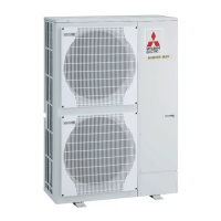
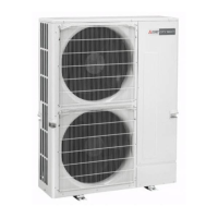
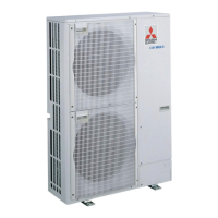
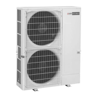
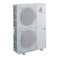
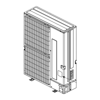
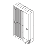
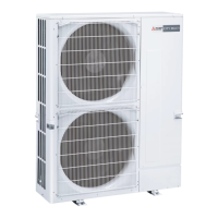
OUTDOOR UNIT
No. OCH446
REVISED EDITION-B
[Service Ref.]
PUMY-P100VHMB PUMY-P100VHMBR1 PUMY-P100VHMBR2
PUMY-P125VHMB PUMY-P125VHMBR1 PUMY-P125VHMBR2
PUMY-P140VHMB PUMY-P140VHMBR1 PUMY-P140VHMBR2
PUMY-P100VHMB-BS PUMY-P100VHMBR1-BS PUMY-P100VHMBR2-BS
PUMY-P125VHMB-BS PUMY-P125VHMBR1-BS PUMY-P125VHMBR2-BS
PUMY-P140VHMB-BS PUMY-P140VHMBR1-BS PUMY-P140VHMBR2-BS
PUMY-P100YHMB PUMY-P100YHMBR1 PUMY-P100YHMBR2
PUMY-P125YHMB PUMY-P125YHMBR1 PUMY-P125YHMBR2
PUMY-P140YHMB PUMY-P140YHMBR1 PUMY-P140YHMBR2
PUMY-P100YHMB-BS PUMY-P100YHMBR1-BS PUMY-P100YHMBR2-BS
PUMY-P125YHMB-BS PUMY-P125YHMBR1-BS PUMY-P125YHMBR2-BS
PUMY-P140YHMB-BS PUMY-P140YHMBR1-BS PUMY-P140YHMBR2-BS
HFC
utilized
R410A
September 2010
NOTE :
· This service manual describes technical data of outdoor unit. As for indoor units, refer to its service manual.
· RoHS compliant products have <G> mark on spec name plate.
· For servicing of RoHS compliant products, refer to RoHS PARTS LIST.
[Model name]
<Outdoor unit>
PUMY-P100VHMB
PUMY-P125VHMB
PUMY-P140VHMB
PUMY-P100VHMB-BS
PUMY-P125VHMB-BS
PUMY-P140VHMB-BS
PUMY-P100YHMB
PUMY-P125YHMB
PUMY-P140YHMB
PUMY-P100YHMB-BS
PUMY-P125YHMB-BS
PUMY-P140YHMB-BS
Model name
indication
PARTS CATALOG (OCB446)
Revision :
· PUMY-P100, 125, 140V/YHMBR2(-BS) are added in REVISED EDITION-B.
· Some descriptions have been modified.
· Please void OCH446 REVISED EDITION-A.