EasyManua.ls Logo

Mitsubishi Electric PUMY-P125VMA User Manual

Mitsubishi Electric PUMY-P125VMA
92 pages
To Next Page IconTo Next Page
Page #1 background imageLoading...
Page #1 background image
TECHNICAL & SERVICE MANUAL
CONTENTS
1. TECHNICAL CHANGE ·····································2
2. SAFETY PRECAUTION····································3
3. OVERVIEW OF UNITS······································5
4. SPECIFICATIONS·············································8
5. DATA ·······························································10
6. OUTLINES AND DIMENSIONS······················18
7. WIRING DIAGRAM ·········································19
8.
NECESSARY CONDITIONS FOR SYSTEM CONSTRUCTION
···22
9. TROUBLESHOOTING ····································34
10. ELECTRICAL WIRING····································72
11. REFRIGERANT PIPING TASKS·····················75
12. DISASSEMBLY ···············································80
13. PARTS LIST ····················································86
Outdoor unit
[Model name] [Service Ref.]
PUMY-P125VMA PUMY-P125VMA
PUMY-P125YMA PUMY-P125YMA
PUMY-P125YMA
1
No.OC272
REVISED EDITION-A
2003
SPLIT-TYPE, HEAT PMUP AIR CONDITIONERS
R407C
Revision :
PUMY-P125VMA and
PUMY-P125YMA1 are
added in REVISED
EDITION-A.
Please void OC272.
OUTDOOR UNIT
OC272A--1.qxp 03.9.4 11:06 AM Page 1
Question and Answer IconNeed help?

Do you have a question about the Mitsubishi Electric PUMY-P125VMA and is the answer not in the manual?
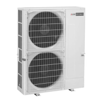
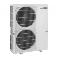
Mitsubishi Electric PUMY-P125VMA Specifications

General IconGeneral
ModelPUMY-P125VMA
Cooling Capacity12.5 kW
Heating Capacity14.0 kW
RefrigerantR410A
TypeHeat Pump

Summary

TECHNICAL CHANGE

SAFETY PRECAUTION

SPECIFICATIONS

WIRING DIAGRAM

NECESSARY CONDITIONS FOR SYSTEM CONSTRUCTION

TRANSMISSION SYSTEM SETUP

Outlines the setup requirements for transmission systems, including wiring and address settings.

REFRIGERANT SYSTEM DIAGRAM

Illustrates the refrigerant system diagram, including piping specifications and component details.

SYSTEM CONTROL

Details system control methods using M-NET and MA remote controllers for various system configurations.

TROUBLESHOOTING

CHECK POINTS FOR TEST RUN

Provides procedures and checks for performing a test run of the air conditioning system.

Special Function Operation and Settings (for M-NET Remote Controller)

Explains special functions and settings for M-NET remote controllers, including group and paired settings.

Countermeasures for Error During Test Run

Lists error codes and their corresponding countermeasures during test run operations.

Remote controller diagnosis

Details the diagnosis function for MA remote controllers when units do not operate correctly.

Remote controller trouble

Describes common symptoms and troubleshooting steps for remote controller issues.

INTERNAL SWITCH FUNCTION TABLE

Provides tables for internal switch functions on the outdoor unit for configuration and operation.

HOW TO CHECK THE PARTS

Guides on how to check various parts, including thermistors, fan motors, and valves, using a tester.

ELECTRICAL WIRING

REFRIGERANT PIPING TASKS

REFRIGERANT PIPING SYSTEM

Details the refrigerant piping system, including line-branch and header-branch methods, and pipe selection.

PRECAUTIONS AGAINST REFRIGERANT LEAKAGE

Outlines precautions against refrigerant leakage, including concentration limits and confirmation procedures.

Related product manuals