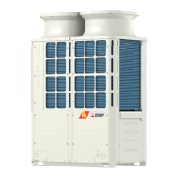
Do you have a question about the Mitsubishi Electric PURY-P72TYJMU-A and is the answer not in the manual?
| Model | PURY-P72TYJMU-A |
|---|---|
| Category | Air Conditioner |
| Manufacturer | Mitsubishi Electric |
| Heating Capacity | 8.0 kW |
| Power Supply | 380-415V, 3-phase |
| Refrigerant | R410A |
| Outdoor Unit Noise Level | 58 dB(A) |
| Voltage (V) | 380-415V |
| Hertz (Hz) | 50 Hz |
| Operating Temperature Range (Heating) | -15°C to 24°C |
| Phase | 3 |
| Operating Temperature Range (Cooling) | -5°C to 46°C |
Initial checks and safety precautions before servicing refrigerant systems.
Lists tools and materials required for R410A installation and servicing.
Specifies approved copper pipe materials and radial thickness for R410A systems.
Procedures for achieving and verifying vacuum degree in the refrigerant system.
Guidelines for charging R410A refrigerant in liquid phase for system safety and performance.
Instructions for setting DIP switches and addresses for various units and controllers.
Compares MA and ME remote controllers' functions, settings, and wiring.
Detailed wiring diagrams for outdoor units (PURY-P72TJMU-A, PURY-P96TJMU-A, etc.).
Wiring diagrams for BC controllers (CMB-P104NU-G, CMB-P105,106NU-G, etc.).
Schematic diagrams of refrigerant circuits for various outdoor units (PURY-P72, P96, P120, P144, etc.).
Details DIP switch functions and factory settings for outdoor units and INV boards.
Pre-test run checklist including refrigerant leak, wiring, and power supply checks.
Step-by-step procedure for performing a test run using the MA remote controller.
Comprehensive list of error codes, their definitions, and the units affected.
Procedures for interpreting and responding to error codes displayed on the remote controller.
Procedures for locating and repairing refrigerant leaks in both cooling and heating seasons.


