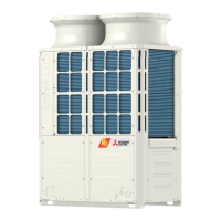
How to fix abnormal bus voltage rise in Mitsubishi Electric PURY-P168 Air Conditioner?
- SShannon LevySep 7, 2025
If your Mitsubishi Electric Air Conditioner is experiencing an abnormal bus voltage rise, monitor and control the voltage output.

How to fix abnormal bus voltage rise in Mitsubishi Electric PURY-P168 Air Conditioner?
If your Mitsubishi Electric Air Conditioner is experiencing an abnormal bus voltage rise, monitor and control the voltage output.
What to do if Mitsubishi Electric Air Conditioner has overload protection?
If your Mitsubishi Electric Air Conditioner is experiencing overload protection issues, assess the load conditions and reduce the load if necessary.
How to fix heatsink overheat protection in Mitsubishi Electric Air Conditioner?
If your Mitsubishi Electric Air Conditioner is experiencing heatsink overheat protection, check the cooling systems and make sure there is adequate airflow.
How to fix RPM error/motor error in Mitsubishi Electric Air Conditioner?
If you are getting an RPM error or motor error on your Mitsubishi Electric Air Conditioner, check the motor operation. Replace the motor if it is faulty.
How to fix temperature sensor fault in Mitsubishi Electric PURY-P168 Air Conditioner?
If there is a temperature sensor fault in your Mitsubishi Electric Air Conditioner, replace the faulty temperature sensors.
How to fix communication error between device and transmission processors in Mitsubishi Electric Air Conditioner?
To resolve a communication error between the device and transmission processors in your Mitsubishi Electric Air Conditioner, check the wiring connections and replace any damaged cables.
What to do if Mitsubishi Electric PURY-P168 Air Conditioner has water supply cutoff?
If the water supply is cutoff to your Mitsubishi Electric Air Conditioner, verify that the water supply is active and the connections are secure.
How to fix transmission power supply fault in Mitsubishi Electric PURY-P168?
If there is a transmission power supply fault in your Mitsubishi Electric Air Conditioner, inspect the power supply connections.
What to do if Mitsubishi Electric Air Conditioner has discharge temperature fault?
If your Mitsubishi Electric Air Conditioner is showing a discharge temperature fault, inspect the discharge temperature sensor for failure.
How to fix serial communication error in Mitsubishi Electric Air Conditioner?
To resolve a serial communication error in your Mitsubishi Electric Air Conditioner, check the wiring connections and replace any damaged cables.
| Refrigerant | R410A |
|---|---|
| Sound Pressure Level (Outdoor Unit) | 60 dB(A) |
| Dimensions (Outdoor Unit) | 1338 x 1050 x 330 mm |
| Series | PURY |
| Type | Air Conditioner |
| Power Source | 380-415V, 50Hz |
Ensuring proper installation, qualified personnel, correct wiring, and electrical safety measures.
Precautions for refrigerant leaks, unit modifications, and handling hazardous parts.
List of essential tools and materials required for installation and servicing.
Specifications for refrigerant piping materials, including types and radial thickness.
Procedures and precautions for brazing refrigerant piping.
Detailed procedure for vacuum drying the refrigerant circuit.
Comparison of chemical properties, pressure, and safety of R410A vs. conventional refrigerants.
Overview of compatible indoor units for various outdoor unit models.
Details on control wiring types, cable sizes, and maximum allowable lengths.
Configuration of switches and addresses for system components.
Wiring and setup example for a system using an MA remote controller.
Diagram illustrating typical system connection with an ME remote controller.
Wiring diagram and cautions for a single outdoor unit system with auto address setup.
Important cautions regarding remote controller connection and system configuration.
Wiring diagram for an ME remote controller system with one outdoor unit.
Important cautions for connecting ME remote controllers and transmission boosters.
Wiring diagram for a system using both MA and ME remote controllers.
Important cautions for systems with mixed MA and ME remote controllers.
Piping length restrictions for systems with a main BC controller.
Front view and refrigerant circuit diagram of outdoor units.
Internal layout and components of the outdoor unit's control box.
Detailed layout of the outdoor unit's control and M-NET boards.
Diagrams of BC controller components for different models.
Comparison of functions and specifications for MA and ME remote controllers.
Procedure for setting up groups and interlocks using the ME remote controller.
Procedure for setting interlocks between LOSSNAY units and indoor units using MA remote controller.
Detailed electrical wiring diagram for the outdoor unit.
Electrical wiring diagram for the BC controller.
Schematic diagrams of the refrigerant circuit for different outdoor unit models.
Description of the function and specifications of key refrigerant circuit components.
Explanation of dipswitch functions and factory settings for outdoor unit control boards.
Explanation of outdoor unit control methods, startup sequences, and bypass controls.
Methods for controlling BC controller functions like solenoid valves and LEV.
Flowcharts illustrating operation mode determination for indoor, outdoor, and BC controller units.
Pre-test run checks for refrigerant leaks, wiring, valves, and power supply.
Step-by-step guide for performing a test run using the MA remote controller.
Procedure for adjusting refrigerant amount based on observed symptoms.
Detailed steps for adjusting refrigerant amount using the service mode.
Reference data for standard operating conditions across different models.
Comprehensive list of error codes, their definitions, and corresponding searched units.
Troubleshooting steps for responding to error codes displayed on the remote controller.
Methods for analyzing transmission wave patterns and identifying noise interference.
Detailed troubleshooting procedures for key components like sensors and valves.
Procedures for identifying and repairing refrigerant leaks.
Step-by-step guide for removing and replacing the compressor.
Procedures for servicing the BC controller, including control box and thermistor replacement.
Guide to interpreting outdoor unit LED display for error codes and status.


