EasyManua.ls Logo

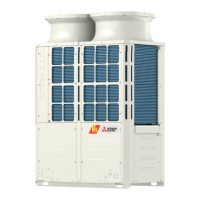
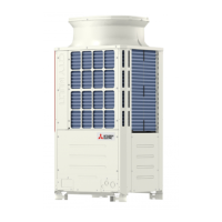
Mitsubishi Electric PURY-P144TKMU-A User Manual

Mitsubishi Electric PURY-P144TKMU-A
403 pages
To Next Page IconTo Next Page
Page #1 background imageLoading...
Page #1 background image
7th
AIR CONDITIONER
2017
Service Handbook
PURY-P72, P96, P120, P144T(Y)KMU-A, P144YSKMU-A
PURY-P168, P192, P216, P240, P264, P288T(Y)SKMU-A
PURY-P72, P96, P120, P144T(Y)KMU-U, P144YSKMU-U
PURY-P168, P192, P216, P240, P264, P288T(Y)SKMU-U
Model

Questions and Answers:

Mitsubishi Electric PURY-P144TKMU-A Specifications

General IconGeneral
Cooling Capacity14.0 kW
Cooling Capacity (BTU/h)47, 800 BTU/h
Heating Capacity16.0 kW
Heating Capacity (BTU/h)54, 600 BTU/h
Phase3
RefrigerantR410A
Operating Temperature (Cooling)-5 to 46°C
Voltage (V)380-415 V
Hertz (Hz)50 Hz
Power SupplyThree-phase

Summary

Safety Precautions

I Read Before Servicing

Necessary Tools and Materials

Lists essential tools for R410A use, tools with restrictions, and tools that must not be used.

Vacuum Drying (Evacuation)

Procedures for using vacuum pumps, standard vacuum degrees, evacuation time, and special vacuum drying.

Refrigerant Charging

Explains reasons for charging in liquid phase and notes on cylinder usage.

II Restrictions

Switch Settings and Address Settings

Explains switch settings for various units and controllers, and how to set addresses.

III Outdoor Unit Components

Control Box of the Outdoor Unit

Provides a diagram and detailed notes on the control box for various outdoor unit models.

V Electrical Wiring Diagram

Electrical Wiring Diagram of the Outdoor Unit

Provides detailed wiring diagrams for the outdoor unit, including symbols and explanations.

VI Refrigerant Circuit

Refrigerant Circuit Diagram

Shows refrigerant circuit diagrams for various outdoor unit models, illustrating component connections.

VII Control

Functions and Factory Settings of the Dipswitches

Details the functions and factory settings of DIP switches on the outdoor unit's control board.

VIII Test Run Mode

Items to be checked before a Test Run

Lists checks for refrigerant leaks, loose connections, control box safety, insulation resistance, and valve status.

Test Run Method

Step-by-step guide on performing a test run using the MA remote controller, including procedures.

Adjusting the Refrigerant Amount

Details symptoms of over/undercharging and the process for adjusting refrigerant amount.

IX Troubleshooting

Error Code Lists

Lists error codes, their definitions, and the units where they occur.

Responding to Error Display on the Remote Controller

Details how to respond to specific error codes, including causes and remedies.

Refrigerant Leak

Provides detailed procedures for identifying and repairing refrigerant leaks.

Troubleshooting Using the Outdoor Unit LED Error Display

Explains how to interpret LED displays on the outdoor unit board for error codes and status.

X LED Monitor Display on the Outdoor Unit Board

How to Read the LED on the Service Monitor

Explains how to interpret the 7-segment LED display and flag displays on the service monitor.

Related product manuals