Do you have a question about the Mitsubishi Electric PURY-80TMU and is the answer not in the manual?
| Model | PURY-80TMU |
|---|---|
| Category | Air Conditioner |
| Refrigerant | R410A |
| Refrigerant Type | R410A |
| Power Supply | 3-Phase |
| Indoor Unit Type | Not applicable (Outdoor Unit) |
| Outdoor Unit Type | Outdoor Unit |
| Indoor Unit Noise Level | Not applicable (Outdoor Unit) |
| Indoor Unit Dimensions (HxWxD) | Not applicable (Outdoor Unit) |
| Indoor Unit Weight | Not applicable (Outdoor Unit) |
Guidelines for safe installation and electrical connections, emphasizing user safety.
Explanation of warning and caution symbols used in the manual for safety.
Explanation of symbols used in diagrams and illustrations within the manual.
Instructions for proper storage of piping materials to prevent contamination and damage.
Guidelines for brazing refrigerant pipes, emphasizing the prevention of foreign matter entry.
Procedure for conducting an airtightness test using nitrogen to ensure system integrity.
Instructions for vacuuming the refrigerant system to remove moisture and non-condensable gases.
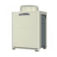
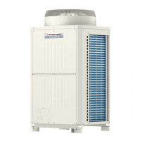
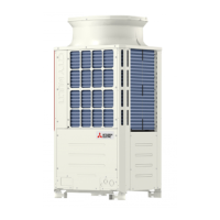
Illustrations and identification of the main external components of the outdoor unit.
Diagram showing the refrigerant circuit and location of thermal sensors.
Schematic showing electrical connections and component layout.
Table of standard operating parameters for cooling and heating modes.
Description of DIP switch and rotary switch functions for unit configuration.
Checkpoints to perform before initiating the system test run.
Explanation of switch operations for registering indoor units with the remote controller.
Details on the initial processing, starting, and capacity control of the outdoor unit.
Explanation of the control logic for solenoid valves and expansion valves.
Flowcharts illustrating the operational logic for outdoor and indoor units.
Overview of key component functions, applications, and specifications.
Relationship between refrigerant amount and system performance characteristics.
Troubleshooting guide for key components like pressure sensors and solenoid valves.
Diagnosis and solutions for issues related to the remote controller and communication.
Detailed troubleshooting based on error codes displayed by the system.
Explanation of LED indicators on the control board for monitoring unit status.
Procedure for locating and repairing refrigerant leaks in piping or indoor units during cooling.
Procedure for locating and repairing refrigerant leaks in the outdoor unit during cooling.
Procedure for locating and repairing refrigerant leaks in piping or indoor units during heating.
Procedure for locating and repairing refrigerant leaks in the outdoor unit during heating.