Do you have a question about the Mitsubishi Electric PURY-100TMU and is the answer not in the manual?
| Series | PURY |
|---|---|
| Refrigerant | R410A |
| SEER | 16.5 |
| Indoor Unit Noise Level | 24 dB |
| Noise Level (Indoor Unit) | 24 dB |
Store pipes indoors to prevent dirt, waste, or water infiltration. Seal ends before brazing.
Special care needed to prevent foreign matter entry into the refrigerant circuit. Use non-oxide brazing.
Pressurize with nitrogen to design pressure. Judge airtightness considering temperature variations.
Use a pump reaching 65 Pa or below. Ensure required accuracy of vacuum gauge and evacuating time.
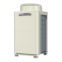
Illustrates the external and internal parts of the outdoor unit, including fan, heat exchanger, compressor, and control box.
Provides a schematic of the refrigerant circuit, including solenoid valves, heat exchangers, and thermal sensors.
Presents the overall electrical wiring diagram for the system, including symbols and their meanings.
Presents standard operation data for cooling mode, including ambient temperature, piping, and pressures for different models.
Explains the function of DIP switches and rotary switches on the outdoor unit for various settings.
Outlines pre-test run checks, including refrigerant leaks, wiring, megger tests, and ball valve status.
Lists check points for test runs with optional parts like drain water lifting-up mechanisms and humidifiers.
Details checks for drain water lifting-up mechanism, float switch, and electric wiring during assembly.
Covers checks for system structure related to installation and piping, including refrigerant piping length and insulation.
Provides step-by-step instructions for performing a test run, including button operations and expected displays.
Explains the functions of various switches on the remote controller for unit registration and settings.
Describes the unit attribute display on the remote controller during registration and connection information retrieval.
Details the procedure for registering indoor units with the remote controller, including setting addresses and confirming registration.
Explains initial processing, start control, and bypass/capacity control mechanisms involving solenoid valves.
Explains the control of solenoid valves (SVA, SVB, SVC) and LEV based on operating modes.
Provides a flowchart for the outdoor unit's operation, detailing normal operations, error modes, and stops.
Lists major outdoor unit components like compressor, pressure sensors, and thermistors with their applications and specifications.
Provides graphs showing the resistance values of temperature sensors at different temperatures for troubleshooting.
Explains the relationship between refrigerant amount and operating characteristics like discharge temperature and compressor shell temperature.
Describes symptoms of refrigerant overcharge or insufficiency and how to adjust refrigerant volume.
Outlines the procedure for adjusting refrigerant amount, including notes on heating mode and charging with liquid refrigerant.
Explains procedures for total replacement or replenishment of refrigerant, including evacuation and charge.
Covers troubleshooting of pressure sensors, including failure judgment methods and sensor configuration.
Lists symptoms, causes, and checking methods for remote controller issues like no start or display errors.
Explains symptoms of noise on the transmission line and methods to confirm wave shape using an oscilloscope.
Guides on troubleshooting inverter and compressor issues based on error codes, including checks and replacement procedures.
Lists failure judgment methods for components like Diode Stack, IPM, Electromagnetic Contactor, DC Reactor, Fan, and Power board.
Outlines a troubleshooting flow for the BC controller's pressure sensor, including checks and corrective actions.
Provides a troubleshooting flow for temperature sensors, including resistance checks and board replacement.
Presents a troubleshooting flow for LEV and solenoid valves, covering operation checks and control issues.
Outlines troubleshooting steps for solenoid valves, including wiring checks, magnetic force tests, and temperature differentials.
Provides step-by-step instructions and illustrations for removing the service panel of the BC controller.
Details procedures for accessing and checking components within the control box, including precautions.
Explains how to check and replace thermistors for liquid and gas piping temperature detection.
Details how to check and replace pressure sensors, emphasizing leak checks before replacement.
Outlines procedures for checking and replacing the LEV, with important notes on service space and lowering the unit.
Provides steps for removing and servicing solenoid valve coils, including disassembly and torque specifications.
Details self-diagnosis for serial transmission abnormality (0403), including causes and checking methods.
Covers multiple address errors (6600) and transmission processor hardware errors (6602), including causes and countermeasures.
Details total capacity error (7100), capacity code error (7101), and connected unit count over (7102) errors.
Explains how to interpret LED displays on the control circuit board for observing unit operating conditions.
Details steps for locating and repairing refrigerant leaks in extension piping or indoor units during cooling.
Provides steps for locating and repairing refrigerant leaks in the outdoor unit during cooling mode.
Explains the procedure for locating and repairing refrigerant leaks in extension piping or indoor units during heating.
Details steps for locating and repairing refrigerant leaks in the outdoor unit during heating mode.