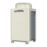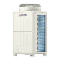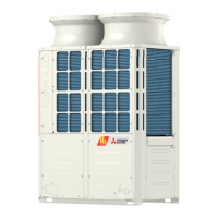
Do you have a question about the Mitsubishi Electric PURY-P250YLM-A(1) and is the answer not in the manual?
| Brand | Mitsubishi Electric |
|---|---|
| Model | PURY-P250YLM-A(1) |
| Category | Air Conditioner |
| Language | English |
General safety guidelines for installation and operation to prevent risks.
Steps and tools required for preparing piping work, including material checks and cleaning.
Information on handling piping materials, refrigerants, and oils, including their properties and compatibility.
Procedures for brazing, leak testing, vacuum drying, and charging refrigerant for piping systems.
Safety guidelines and precautions for electrical wiring work, including component handling and terminal tightening.
Detailed electrical wiring diagrams for outdoor units, illustrating connections between components.
Electrical wiring diagrams for BC controllers, showing connections to indoor units and power supply.
Detailed methods for performing test runs using MA and ME remote controllers, including checks and procedures.
Procedures for evaluating and adjusting refrigerant charge, including calculation formulas and charts.
Detailed definitions and solutions for error codes in the 0-999 range, covering communication and sensor faults.
Definitions and solutions for error codes in the 1000-1999 range, focusing on temperature and pressure faults.
Definitions and solutions for error codes in the 2000-2999 range, related to drain pump and water leakage issues.
Definitions and solutions for error codes in the 4000-4999 range, covering power supply, motor, and function errors.
Definitions and solutions for error codes in the 5000-5999 range, related to various sensor and circuit faults.
Definitions and solutions for error codes in the 6000-6999 range, related to communication and address errors.
Definitions and solutions for error codes in the 7000-7999 range, covering capacity, address, and model setting errors.
Common problems related to refrigerant control, such as capacity issues and irregular outdoor unit stops.
Procedures for troubleshooting issues with solenoid valves (SVA, SVB, SVC, SV4a-d, SV7, SV9, SV10, SV11).
Steps for diagnosing and resolving problems with electric expansion valves (LEVs) on indoor units, BC controllers, and outdoor units.
Comprehensive troubleshooting procedures for inverter-related issues, including circuit components and damage checks.
Procedures for identifying, repairing, and managing refrigerant leaks in extension pipes and outdoor units.


 Loading...