Do you have a question about the Mitsubishi Electric PURY-P288 and is the answer not in the manual?
| Brand | Mitsubishi Electric |
|---|---|
| Model | PURY-P288 |
| Category | Air Conditioner |
| Language | English |
Read and observe all safety precautions before installing and operating the unit.
Guidelines for using R410A refrigerant, including piping, tools, and handling.
Avoid hazardous locations and take measures for hospitals and unusual environments.
Ensure proper grounding, wiring, and circuit breaker usage for safety.
Exercise caution during product transport and proper disposal of packing materials.
Prepare for test run by turning unit on early and avoiding electrical hazards.
Check the type of refrigerant used in the system to be serviced.
Prepare the following tools and materials necessary for installing and servicing the unit.
Use refrigerant pipes made of phosphorus deoxidized copper.
Store the pipes to be used indoors. (Warehouse at site or owner's warehouse)
Use a small amount of ester oil, ether oil, or alkylbenzene to coat flares and flanges.
No changes have been made in the brazing procedures. Perform brazing with special care to keep foreign objects (such as oxide scale, water, and dust) out of the refrigerant system.
No changes have been made in the detection method. Note that a refrigerant leak detector for R22 will not detect an R410A leak.
To prevent the vacuum pump oil from flowing into the refrigerant circuit during power OFF or power failure, use a vacuum pump with a reverse-flow check valve.
R410A is a pseudo-azeotropic HFC blend (boiling point R32=-52°C[-62°F], R125=-49°C[-52°F]) and can almost be handled the same way as a single refrigerant, such as R22.
If the refrigerant leaks out, it may be replenished. The entire refrigerant does not need to be replaced.
As with R22, the new refrigerant (R410A) is low in toxicity and chemically stable nonflammable refrigerant.
HFC type refrigerants use a refrigerating machine oil different from that used in the R22 system.
Table summarizing compatible indoor units for different outdoor units.
Details on M-NET transmission and remote controller wiring types and maximum lengths.
Instructions for setting DIP switches and addresses for system configuration.
Illustrations of typical system connections with MA and ME remote controllers.
System wiring examples for MA remote controller connection.
System wiring examples for ME remote controller connection.
System wiring examples for mixed MA and ME remote controller setups.
Diagrams and tables detailing pipe length restrictions for BC controller systems.
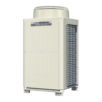
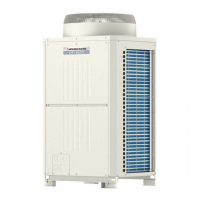
Front view and refrigerant circuit diagrams of various outdoor unit models.
Location and function of components within the outdoor unit's control box and circuit board.
Detailed diagram of the outdoor unit's main control board.
Identification and diagrams of BC controller components, control box, and circuit board.
Diagram of the BC controller's control box.
Diagram of the BC controller circuit board.
Comparison of functions, specifications, and selection criteria for MA and ME remote controllers.
Procedure for setting up groups and interlocks using the ME remote controller.
Procedure for setting up LOSSNAY interlocks with the MA remote controller.
Instructions for using the remote controller's built-in temperature sensor for temperature detection.
Wiring diagrams for various outdoor unit models (PURY-P72TKMU-A, PURY-P96TKMU-A, etc.).
Wiring diagrams for BC controller models (CMB-P104NU-G, CMB-P105,106NU-G, etc.).
Wiring diagram for the transmission booster unit.
Schematic diagrams of the refrigerant circuit for various outdoor unit models.
Description of key components and their functions in the outdoor unit and BC controller.
Details on the functions and factory settings of DIP switches on the control board and INV board.
Explanation of control methods, including initial control, startup sequence, and bypass control.
Control logic for solenoid valves (SVA, SVB, SVC) and LEV operation based on mode.
Flowcharts illustrating mode determination for indoor units, outdoor units, and BC controllers.
Check refrigerant leaks, loose connections, insulation resistance, and power supply before test run.
Step-by-step guide for performing a test run using the MA remote controller.
Understand operating characteristics and adjust refrigerant amount based on symptoms and tables.
Overcharging or undercharging of refrigerant can cause the following symptoms:
Follow the procedures below to add or extract refrigerant as necessary depending on the operation mode.
List of normal operating symptoms that do not indicate a malfunction.
Reference data for standard operating conditions (cooling and heating) for various models.
Comprehensive list of error codes, their definitions, and the units affected.
Troubleshooting steps for specific error codes displayed on the remote controller.
Procedure for investigating transmission line issues, including wave shape and noise analysis.
Troubleshooting guides for major components like pressure sensors, thermistors, and solenoid valves.
Procedures for locating and repairing refrigerant leaks in different parts of the system.
Step-by-step guide for safely replacing the compressor unit.
Procedures for servicing the BC controller, including control box and service panel removal.
Interpreting LED error displays on the outdoor unit board for troubleshooting.
Guide to understanding numerical and flag displays on the service monitor.
Information displayed on the monitor screen during initial settings and after completion.
Explanation of the outdoor unit's clock function and error history storage.