Do you have a question about the Mitsubishi Electric PURY-P200YMF-C and is the answer not in the manual?
| Brand | Mitsubishi Electric |
|---|---|
| Model | PURY-P200YMF-C |
| Category | Air Conditioner |
| Language | English |
Guidelines for safe installation, electrical work, and understanding safety symbols.
Precautions for using R407C, including handling, storage, and avoiding contamination.
Proper storage and sealing of piping materials to prevent contamination.
Procedures for machining pipes and applying specific oils, emphasizing minimum quantity.
Lists necessary apparatus and materials, comparing R407C with R22 usage.
Brazing methods and strict observations to prevent foreign matter entry into the refrigerant circuit.
Steps for conducting airtightness tests and vacuuming operations for the refrigerant system.
Procedures for charging refrigerant and replacing the dryer unit for R407C systems.
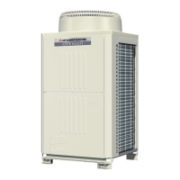
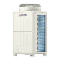
Visual identification of components within outdoor units for various models.
Visual details of components for PURY models, including valve blocks and circuits.
Identification of boards and components within the controller box assembly.
Detailed labeling of connectors, switches, and LEDs on the main board.
Identification of connectors and components on the inverter board.
Identification of connectors on the FANCON and G/A boards.
Labels for connectors and switches on the BC controller board.
Visual representation of the Relay 10 and Relay 4 boards.
Diagram illustrating the refrigerant flow and component layout for PUHY models.
Diagram showing the refrigerant circuit for PUY models.
Refrigerant circuit diagram for PUHY-P models.
Refrigerant circuit diagram for PUY-P models.
Refrigerant circuit and component blocks for PURY models.
Refrigerant circuit diagram for PURY-P models with component blocks.
Detailed electrical wiring diagram for PU(H)Y models, including symbol explanations.
Electrical wiring diagram for PURY-(P) models with component identification.
Electrical wiring for CMB-P104V-E, including symbol explanations and notes.
Electrical wiring diagram for CMB-P105V-E, with notes on terminal blocks and SVM.
Electrical wiring for CMB-P106V-E, detailing wiring and notes.
Wiring schematic for CMB-P108V-E, including symbol explanations and SVM notes.
Electrical wiring diagram for CMB-P1010V-E, with notes on transmission terminal blocks and SVM.
Electrical wiring for CMB-P1013V-E, including symbol explanations and notes.
Electrical wiring diagram for CMB-P1016V-E, detailing symbols and notes.
Standard operating parameters for PU(H)Y models during cooling operation.
Standard operating data for PU(H)Y-P models during cooling.
Standard operating parameters for PURY models during cooling.
Standard heating operation data for PUHY-P models, covering various parameters.
Heating operation data for PUHY-P models, including temperatures and pressures.
Heating operation parameters for PURY models, covering various parameters.
Heating operation parameters for PURY-P models, including temperatures and pressures.
Explains the functions of DIP switches (SWU, SW1, SW2, SW3, SW4) on the outdoor unit.
DIP switch settings and functions for PUHY-P outdoor units.
DIP switch configurations for PURY outdoor units, detailing functions and settings.
DIP switch settings and functions for PURY-P outdoor units.
Explains DIP switch settings for indoor units across various series and models.
Details DIP switch settings (SW4, SW5) for various indoor unit models and functions.
Essential checks before test run and cautions for inverter operation.
Specific checks for optional parts and drain water lifting-up mechanisms during test runs.
Step-by-step instructions for performing the test run operation and interpreting results.
Checks related to system structure, installation, and piping for troubleshooting.
Checks for transmission lines, power wiring, and grounding for proper system operation.
Checks for system setup, address settings, and remote controller communication.
Explains the functions of remote controller switches for unit registration and group setup.
Describes unit attribute display and the process of registration, deletion, and retrieval.
Step-by-step procedure for registering indoor units into groups using the remote controller.
Methods for retrieving group registration information and specific unit registration data.
Procedures for deleting group registration information from the remote controller.
Procedure for deleting address information that does not exist, often due to errors.
Explains initial processing, start control, and bypass/capacity control for the outdoor unit.
Details on frequency control, including starting, pressure limits, discharge temperature, and bypass valve backup.
Explains control logic for oil return, subcool coils, and defrost operations.
Details defrost control for PURY models and liquid level detection logic.
Explains control logic for BC controller solenoid valves and LEV.
Flow chart detailing the operational logic for the outdoor unit.
Flow chart illustrating the operational logic for the BC controller in PURY systems.
Flow chart detailing the operational logic for indoor units, including modes and prohibitions.
Flow chart explaining the operational sequence and logic during cooling mode.
Flow chart detailing the operational logic for heating mode, including defrosting.
Flow chart illustrating the operational sequence for dry mode.
Details the function, application, specification, and check method for key system components.
Continues listing component functions and specifications, including thermistors and valves.
Details functions and specifications for BC controller components like pressure sensors and solenoids.
Specifications for temperature and pressure sensors used in the BC controller.
Graphs showing the resistance of various temperature sensors at different temperatures.
Explains the relationship between refrigerant amount and system operating characteristics.
Detailed procedure for adjusting and judging refrigerant volume for PU(H)Y models.
Formula and table for calculating additional refrigerant charge based on piping size.
Step-by-step procedure for operating the refrigerant volume adjustment mode.
Flow chart guiding the refrigerant volume adjustment for PUHY-P models.
Procedure for refrigerant volume adjustment mode specific to PURY models.
Flow chart for refrigerant volume adjustment of PURY models, including SC data checks.
Flow chart for refrigerant volume adjustment of PURY-P models, including SC data checks.
Steps to diagnose failures related to pressure sensors using LED monitor and test procedures.
Procedures for checking solenoid valves (SV1-SV4) using self-diagnosis switches and LED indicators.
Troubleshooting steps for solenoid valves SV1-SV6 in PURY models using self-diagnosis.
Details the solenoid valve block configuration and torque specifications for maintenance.
Explains outdoor LEV operation, pulse signals, and valve closing/opening characteristics.
Table of failure modes, judgment methods, treatments, and affected LEVs for linear expansion valves.
Procedure for removing and installing outdoor LEV coils, including important notes.
Information on check valves block for PURY models and associated torque specifications.
Procedures for testing IPM and diode stack components using a tester.
Guide for diagnosing and resolving issues with the remote controller, including LED checks.
Flow chart to troubleshoot remote controller issues, differentiating between MELANS and non-MELANS systems.
Troubleshooting steps for "HO" display issues and communication errors with the remote controller.
Procedure for checking the 30V transmission power circuit for faults.
Methods to investigate transmission line issues by analyzing waveform and noise.
Measures to address noise issues and low wave height values in transmission lines.
Steps for treating inverter and compressor issues based on error codes and symptoms.
Important cautions regarding voltage and current measurements for inverter circuits.
Steps for diagnosing and resolving issues related to the fan motor.
Procedures for troubleshooting issues related to breaker tripping and power supply.
Methods for judging the failure of individual electronic components.
Flow chart for diagnosing and troubleshooting the BC controller's pressure sensor.
Additional notes and precautions for BC controller pressure sensor troubleshooting and replacement.
Flow chart for diagnosing thermistor (temperature sensor) issues.
Thermistor resistance graph and checks using LED monitor display.
Flow charts for diagnosing problems with LEV and solenoid valves.
Details LEV operation, checking conditions, and control characteristics based on pressure and superheat.
Checks for LEV board connections and basic operation characteristics.
Using the self-diagnostic monitor and troubleshooting flow for solenoid valves.
Detailed troubleshooting steps for solenoid valves, including operational coordination and transformer checks.
Explains operation coordination of solenoid valves and BC controller transformer checks.
Step-by-step guide for removing the service panel of the BC controller.
Procedures for accessing and disassembling the control box for various CMB models.
Procedures for removing and replacing thermistors and pressure sensors.
Procedures for servicing LEV and solenoid valve coils, including removal and disassembly.
A comprehensive list of error codes and their corresponding meanings or detected issues.
List of intermittent fault codes and their associated trouble delay contents.
Detailed steps for diagnosing and resolving serial transmission abnormalities.
Guide to troubleshoot discharge temperature abnormalities in the outdoor unit.
Troubleshooting for low pressure saturation and liquid level sensor abnormalities.
Troubleshooting guide for low, high, and intermediate pressure abnormalities.
Steps to diagnose and resolve issues related to overcharged or lacked refrigerant.
Troubleshooting for suction pressure, water leaks, drain pump, and float switch issues.
Steps to resolve reverse phase and power supply sync signal abnormalities.
Guide for troubleshooting fan speed abnormalities and VDC sensor/circuit errors.
Troubleshooting for bus voltage, radiator overheat, overload, and IPM alarm errors.
Steps to diagnose and resolve cooling fan abnormalities.
Troubleshooting for IPM alarm, bus voltage, and overload protection issues.
Guide for troubleshooting various thermal sensor errors related to different components.
Troubleshooting for pressure sensor and IAC sensor/circuit abnormalities.
Troubleshooting for IAC sensor errors and issues with connecting different indoor models.
Guide for resolving communication errors like multiple addresses and transmission processor issues.
Troubleshooting for transmission processor and bus-busy errors, including wave shape analysis.
Steps to resolve communication errors between transmission processors.
Troubleshooting steps for "No ACK error" in single refrigerant systems.
Troubleshooting "No ACK error" for plural refrigerant systems and group operations.
Troubleshooting "No ACK error" in systems connected with MELANS.
Troubleshooting for system errors like total capacity, capacity code, and connected unit count.
Troubleshooting for address setting, connection number, remote control sensor, and model mismatch errors.
Guide on how to interpret the LED indicators on the control circuit board for service monitoring.
Table mapping SW1 settings to LED displays and remarks for PU(H)Y models.
LED display codes and SW1 settings for PU(H)Y-P models.
Table of SW1 settings and corresponding LED displays for various data points (THHS, HPS, etc.).
Further SW1 settings and LED displays for PU(H)Y data.
Further SW1 settings and LED displays for PU(H)Y data, including operation modes.
SW1 settings and LED displays for IC room and liquid pipe temperatures.
SW1 settings and LED displays for IC gas pipe temperatures.
SW1 settings and LED displays for SH and SC values.
SW1 settings and LED displays for operation mode and filter status.
SW1 settings and LED displays for PURY-P models, including error codes and operation modes.
Table showing SW1 settings and corresponding LED displays for PURY-P data.
SW1 settings and LED displays for TH data on PURY-P models.
SW1 settings and LED displays for αOC, Hz, and calibration data.
SW1 settings and LED displays for operation mode and branch number for PURY-P models.
Procedure for finding refrigerant leaks in extension piping or indoor units during cooling.
Procedure for finding refrigerant leaks in piping or indoor units during heating.
Steps to locate and repair refrigerant leaks in the outdoor unit during heating.
Flow chart and notes for checking and calibrating refrigerant composition (αOC) for PURY models.
Detailed notes and calibration procedures for checking refrigerant composition (αOC).