EasyManua.ls Logo

Mitsubishi Electric PUY-SP42VKA User Manual

Mitsubishi Electric PUY-SP42VKA
12 pages
To Next Page IconTo Next Page
Page #1 background imageLoading...
Page #1 background image
SERVICE MANUAL
No.OCH644
SPLIT-TYPE AIR CONDITIONERS
R410A
November 2017
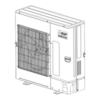
Outdoor unit
[Model Name]
PUY-SP42VKA
PUY-SP48VKA
PUY-SP36YKA
PUY-SP42YKA
PUY-SP48YKA
[Service Ref.]
PUY-SP42VKA.TH(-T/-D/-N)
PUY-SP48VKA.TH(-T/-D/-N)
PUY-SP36YKA.TH(-T/-D/-N)
PUY-SP42YKA.TH(-T/-D/-N)
PUY-SP48YKA.TH(-T/-D/-N)
PARTS CATALOG (OCB644)
CONTENTS
1. REFERENCE MANUAL ································· 2
2. SAFETY PRECAUTION ································· 2
3. SPECIFICATIONS ·········································· 6
4. DATA ······························································· 7
5. OUTLINES AND DIMENSIONS ··················· 10
6. WIRING DIAGRAM ······································ 11
7. WIRING SPECIFICATIONS ·························· 13
8.
REFRIGERANT SYSTEM DIAGRAM
············· 18
9. TROUBLESHOOTING ································· 20
10. FUNCTION SETTING ··································· 77
11.
MONITORING THE OPERATION DATA BY THE REMOTE CONTROLLER
····89
12. EASY MAINTENANCE FUNCTION ············· 99
13. DISASSEMBLY PROCEDURE ··················· 103
Revision:
$GGHG
PUY-SP42/48VKA.TH(-T/-D/-N)
6RPHGHVFULSWLRQVKDYHEHHQ
PRGLILHG
REVISED EDITION-A
2&+LVYRLG
Question and Answer IconNeed help?

Do you have a question about the Mitsubishi Electric PUY-SP42VKA and is the answer not in the manual?

Mitsubishi Electric PUY-SP42VKA Specifications

General IconGeneral
BrandMitsubishi Electric
ModelPUY-SP42VKA
CategoryAir Conditioner
LanguageEnglish

Summary

REFERENCE MANUAL

Indoor Unit Service Manual Model List

Lists indoor unit models and their corresponding service references for repair.

SAFETY PRECAUTION

R410A Refrigerant Safety Cautions

Safety guidelines for R410A refrigerant, covering preparation and repair procedures.

Service Tools for R410A Refrigerant

Exclusive Tool Listing and Specifications

Lists essential service tools specifically for R410A refrigerant and their specifications.

Reusing Existing R22 Refrigerant Pipes

Flowchart for R22 Pipe Reuse Assessment

A flowchart to determine the usability of existing R22 refrigerant pipes with R410A systems.

Refrigerant Piping Work Cautions

R410A Pipe Thickness Requirements

Specifies the necessary thickness for refrigerant pipes when using R410A.

R410A Flare Cutting and Nut Dimensions

Details the precise dimensions for flare cutting and flare nuts for R410A piping.

Tool Compatibility for R410A Piping

Evaluates the compatibility of R22 and R407C tools for R410A refrigerant piping work.

Outdoor Unit Specifications

Power Supply and Electrical Characteristics

Details power supply voltage, phase, current, and electrical input for outdoor units.

Fan Performance and Noise Levels

Information on fan motor output, air volume, and noise level measurements.

Refrigerant Charge and Piping Size

Specifications for refrigerant charge, oil type, and outdoor unit pipe sizes.

Technical Data for Refrigerant Systems

R410A Refrigerant Charge Adjustment Data

Data on refilling refrigerant charge based on piping length for R410A systems.

Compressor Technical Specifications

Provides compressor winding resistance data measured at 20°C.

Standard Operation Data

Cooling Mode Electrical and Capacity Data

Standard operating data including total capacity, input, and current for cooling.

Refrigerant Circuit Operating Parameters

Data on refrigerant discharge/suction pressures and condensing/suction temperatures.

Air Temperature Readings During Operation

Intake and discharge air temperatures for indoor and outdoor units in standard operation.

Unit Outlines and Dimensions

Installation Space and Service Access Requirements

Specifies required free space and service access dimensions around the outdoor unit.

Foundation, Piping, and Wiring Details

Information on foundation bolts, piping, and wiring connection points.

Piping Knock-Out Hole Specifications

Details the size and location of knock-out holes for piping connections.

Wiring Diagrams

Electrical Component Identification

Lists symbols and names for electrical components used in the wiring diagrams.

Model Select Switch Configuration

Guides on setting the model select switches for unit configuration.

Wiring Diagrams for Specific Models

PUY-SP36/42/48YKA Model Wiring

Wiring diagrams for PUY-SP36YKA, PUY-SP42YKA, and PUY-SP48YKA outdoor units.

Model Selection and M-NET Adapter Setup

Instructions for model selection switches and M-NET adapter connections.

Wiring Specifications

Field Electrical Power Wiring Standards

Standards for field electrical wiring, including circuit rating and wire size.

Indoor/Outdoor Connection Cable Requirements

Specifications for indoor/outdoor unit connection cables, including length and type.

Refrigerant System Diagram

Refrigerant Pipe Connections and Flow

Diagram illustrating gas and liquid refrigerant pipe connections and flow paths.

Major Refrigerant System Components

Identifies key components within the refrigerant system, such as valves, sensors, and compressor.

Related product manuals