EasyManua.ls Logo

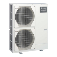
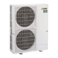
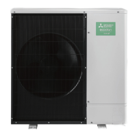
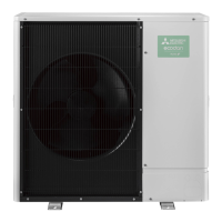
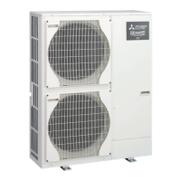
Mitsubishi Electric PUZ-HWM140VHA User Manual

Mitsubishi Electric PUZ-HWM140VHA
74 pages
To Next Page IconTo Next Page
Page #1 background imageLoading...
Page #1 background image
SERVICE MANUAL
CONTENTS
1. REFERENCE MANUAL
...................................
2
2. SAFETY PRECAUTION
...................................
3
3. SPECIFICATIONS
..........................................
10
4. DATA
.............................................................
13
5. OUTLINES AND DIMENSIONS
.....................
14
6. WIRING DIAGRAM
........................................
15
7. WIRING SPECIFICATIONS
...........................
17
8. REFRIGERANT SYSTEM DIAGRAM
...............
18
9. TROUBLESHOOTING
...................................
19
10. DISASSEMBLY PROCEDURE
......................
68
Notes:
This manual describes service
data of outdoor unit only.
R32
PARTS CATALOG (OCB748)
AIR TO WATER HEAT PUMP
No. OCH748
August 2020
<Outdoor unit>
[Model Name]
PUZ-HWM140VHA
PUZ-HWM140YHA
Salt proof model
PUZ-HWM140VHA-BS
PUZ-HWM140YHA-BS
[Service Ref.]
PUZ-HWM140VHA
PUZ-HWM140YHA
PUZ-HWM140VHA-BS
PUZ-HWM140YHA-BS
Questions and Answers:

Mitsubishi Electric PUZ-HWM140VHA Specifications

General IconGeneral
Cooling Capacity (kW)14.0
Heating Capacity (kW)16.0
Coefficient of Performance (COP)4.0
RefrigerantR410A
Sound Pressure Level (Outdoor Unit)52 dB(A)
TypeAir-to-Water Heat Pump
Power Supply3-phase, 400V, 50Hz
Operating Temperature Range (Cooling)-10°C to 46°C

Summary

1. REFERENCE MANUAL

2. SAFETY PRECAUTION

2-1. ALWAYS OBSERVE FOR SAFETY

General safety guidelines for unit operation and maintenance.

2-2. CAUTIONS RELATED TO NEW REFRIGERANT

Specific safety measures for handling R32 refrigerant.

[5] Service tools

List of specialized tools required for R32 refrigerant servicing.

3. SPECIFICATIONS

3-1. SPECIFICATIONS

Technical details and operating conditions of the outdoor units.

4. DATA

4-1. NOISE CRITERION CURVES

Graphical representation of noise levels across frequency bands.

4-2. STANDARD OPERATION DATA

Table of operational parameters for cooling and heating modes.

5. OUTLINES AND DIMENSIONS

1 FREE SPACE (Around the unit)

Required clearance around the unit for installation and airflow.

2 SERVICE SPACE

Minimum space needed for maintenance access to the unit.

3 FOUNDATION BOLTS

Details on foundation bolt type and installation.

6. WIRING DIAGRAM

7. WIRING SPECIFICATIONS

FIELD ELECTRICAL WIRING (power wiring specifications)

Specifications for power and control wiring between units.

8. REFRIGERANT SYSTEM DIAGRAM

9. TROUBLESHOOTING

9-1. TROUBLESHOOTING

Summary of self-diagnosis codes and actions for service.

9-2. CHECKPOINT UNDER TEST RUN

Procedures and checks to perform before starting unit testing.

9-3. SELF-DIAGNOSIS ACTION TABLE

Table correlating check codes with abnormal points, causes, and actions.

9-4. TROUBLESHOOTING OF PROBLEMS

Common operational problems and their corresponding countermeasures.

9-5. HOW TO CHECK THE PARTS

Check Method of DC Fan Motor

Procedure for checking the DC fan motor and related circuit boards.

9-6-1. Thermistor feature chart

Resistance characteristics of various thermistors based on temperature.

9-6-2. High Pressure Sensor

9-6-3. Linear Expansion Valve

(1) Operation summary of the linear expansion valve

Overview of linear expansion valve operation and pulse signal control.

(2) Linear expansion valve operation

Graphical representation of valve position versus pulse number.

(3) How to attach and detach the coil of linear expansion valve

Procedure for removing and installing the linear expansion valve coil.

9-7. TEST POINT DIAGRAM

9-8. OUTDOOR UNIT OPERATION MONITOR FUNCTION

(1)Normal condition

Display patterns of LED1 and LED2 under normal operation.

(2)Abnormal condition

Indication of abnormalities via LED blinking patterns and check codes.

SW2 Settings for Data Display

Configuration of SW2 switches to display various operational data and error codes.

9-9. FUNCTION OF SWITCHES

SW1 Manual Defrost and History Clear

Functions and settings for manual defrost and clearing abnormal history.

SW9 Starting Ambient Temp. Settings

Configuration of ambient temperature thresholds for ZUBADAN blink injection.

9.9.1. Low Noise Mode

9.9.2. Demand Function

9-10. Request Code List

9-10-1. Detail Contents in Request Code

[Operation state] (Request code: "0")

Details on relay output states and operation modes.

[Outdoor unit - Control state] (Request code: "51")

Details on normal, heat operation, and defrost states.

[Compressor - Frequency control state] (Request code: "52")

Details on compressor frequency control states and related protections.

[Actuator output state] (Request code: "54")

Details on the output states of various actuators like SV1, 4-way valve, compressor.

[Error content (U9)] (Request code: "55")

Details on error content related to U9, including voltage and signal errors.

[Outdoor unit - Setting information] (Request code: "71")

Details on defrost mode and unit phase/mode settings.

10. DISASSEMBLY PROCEDURE

1. Removing the service panel and top panel

Steps to remove the service panel and top panel of the unit.

2. Removing the fan motor (MF1, MF2)

Procedure for removing the fan motor components.

3. Removing the electrical parts box

Steps to remove the electrical parts box and its internal components.

4. Disassembling the electrical parts box (PUZ-HWM140Y)

Detailed steps for disassembling the electrical parts box.

6. Removing the thermistor <Discharge> (TH4) and thermistor <Comp. surface> (TH33)

Procedure to remove discharge and surface temperature thermistors.

7. Removing the thermistor <Liquid> (TH3) and thermistor <Suction> (TH32)

Procedure to remove liquid and suction temperature thermistors.

9. Removing the 4-way valve

Procedure for removing the 4-way valve assembly.

10. Removing the LEV

Procedure for removing the Linear Expansion Valve (LEV).

12. Removing high pressure sensor (63HS)

Procedure for removing the high pressure sensor.

13. Removing the plate heat exchanger

Steps to remove the plate heat exchanger.

15. Removing the compressor (MC)

Procedure for removing the compressor unit.

16. Removing the power receiver

Steps to remove the power receiver assembly.

17. Removing the pressure relief valve

Procedure for removing the pressure relief valve (PRV).

Related product manuals