17
OCH809A
6
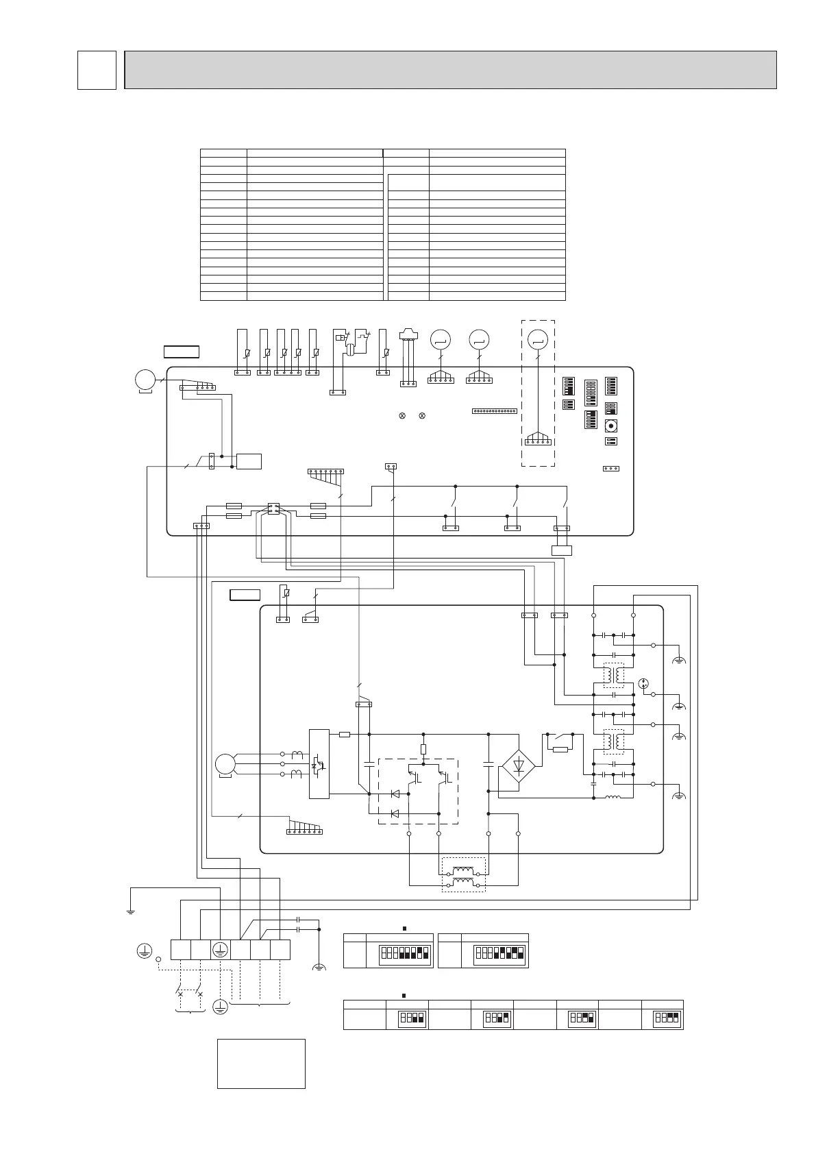
WIRING DIAGRAM
PUZ-SWM60VAA.TR PUZ-SWM80VAA.TR
PUZ-SHWM60VAA.TR PUZ-SHWM80VAA.TR
C. B.
21S4
X51
X52
31
21S4
(GN)
SV3/SS
(WH)
31
X54
31
SV1/CH
(GY)
71
MS
3~
5
CNF1(WH)
MF1
TRANS
CN4
(WH)
CNDC
(PK)
1
2
3
CNS
(WH)
3
1
F2
F1
F3
F4
CNAC
(WH)
1 3
CNDM
(WH)
1 2
2
1
2
3 4
7
CN2
(RD)
1 7
63H
t°
51
LEV-A
(WH)
31
63H
(YE)
31
TH33
(YE)
1 2
t°
1 2
t°
1
4
t° t°
TH3
(WH)
TH7/6
(RD)
LEV-A
M
5
51
LEV-B
(RD)
LEV-B
M
5
51
LEV-C
(BU)
LEV-C
M
5
2 1
t°
TH4
TH4
(WH)
LED1LED2
63HS
(WH)
TH33
TH32
(BK)
TH32 TH7 TH6 TH3
63HS
1 3
CNM
(WH)
1 14
SW4
SW8
SWP
SW1 SW6
SW5
*
1
SW9
SW7
*
3
SYMBOL NAME SYMBOL NAME
TB1
MC
MF1
21S4
63H
63HS
TH3
TH4
TH6
TH7
TH8
TH32
TH33
TRS
LEV-A, LEV-B, LEV-C
DCL
CY1, CY2
Terminal Block <Power Supply, Indoor/Outdoor>
Motor for Compressor
Fan Motor
Solenoid Valve (4-Way Valve)
High Pressure Switch
High Pressure Sensor
Thermistor <Liquid>
Thermistor <Discharge>
Thermistor <2-Phase Pipe>
Thermistor <Ambient>
Thermistor <Heat Sink>
Thermistor <Suction>
Thermistor <Comp. Surface>
Thermal Protector
Linear Expansion Valve
Reactor
Capacitor
C. B. Controller Circuit Board
Switch <Manual Defrost, Defect History Record Reset,
Refrigerant Address>
Switch <Function Switch>
Switch <Function Switch>
Switch <Function Switch, Model Select>
Switch <Function Switch>
Switch <Function Switch>
Switch <Function Switch>
Switch <Pump Down>
Connector <Connection for Option>
Connector <Connection for Option>
Connector <Connection for Option>
Connector <Connection for Option>
Fuse <T10AL250V>
Fuse <T6.3AL250V>
P. B. Power Circuit Board
SW1
SW4
SW5
SW6
SW7
SW8
SW9
SWP
CNDM
SV1/CH
SV3/SS
CNM
F1, F2
F3, F4
P. B.
TO
INDOOR UNIT
OG
BNYE
L N S1 S2 S3
TB1
POWER SUPPLY
~/N
230V 50Hz
RD BU
CNAC2
(RD)
CNAC1
(WH)
LI NI
EI
~
+
-
E3
IC600
CY1
CY2
U
V
W
RD
BK
WH
MC
MS
3~
DCL
BK
3131
E2
E4
TB1A
TB3A
TB1B
TB3B
31
CNDC
(PK)
1 2
t°
TH8
CN6
(WH)
1 7
CN2
(RD)
7
CN4
(WH)
2
1
2
2
BK
BK
BK
BK
U
V
W
IC500
+
~
RD
DS
GNYE
BK
RD
81 2 3 4 5 6 7
OFF
ON
60V
MODEL
SW6 *2
81 2 3 4 5 6 7
OFF
ON
80V
MODEL
SW6 *2
*1 MODEL SELECT
The black square ( ) indicates a switch position.
1 2 3 4
OFF
ON
SW9 *4
Ambient temp.
*4 SW9-1 and SW9-2 : Function Switch
*5 SHWM only
1 2 3 4
OFF
ON
SW9 *4
Ambient temp.
SW9 *4
Ambient temp.
SW9 *4
Ambient temp.
–6°C or less
(Default setting)
0°C or less
1 2 3 4
OFF
ON
1 2 3 4
OFF
ON
–3°C or less
3°C or less
*3 SW9-3 and SW9-4: Function Switch for SHWM only
Ambient temp. of ZUBADAN Flash Injection becomes effective.
The black square ( ) indicates a switch position.
*2 SW6-1 to SW6-3 : Function Switch
*5
Never splice the power
cable or the indoor-outdoor
connection cable,
otherwise it may result in
a smoke, a fire or
communication failure.
[LEGEND]
4 3
12
TRS
 Loading...