EasyManua.ls Logo

Mitsubishi Electric SLZ-KF09NA User Manual

Mitsubishi Electric SLZ-KF09NA
36 pages
To Next Page IconTo Next Page
Page #1 background imageLoading...
Page #1 background image
TECHNICAL & SERVICE MANUAL
CONTENTS
1. REFERENCE MANUAL
......................
2
2. SAFETY PRECAUTION ......................2
3. PARTS NAMES AND FUNCTIONS
.....
4
4. SPECIFICATIONS
...............................
9
5. OUTLINES AND DIMENSIONS
.........
11
6. WIRING DIAGRAM
............................
13
7.
REFRIGERANT SYSTEM DIAGRAM
.....
14
8. TROUBLESHOOTING
.......................
15
9. SPECIAL FUNCTION
........................
28
10. 4-WAY AIRFLOW SYSTEM
...............
30
11. DISASSEMBLY PROCEDURE
..........
32
Indoor unit
[Model Name] [Service Ref.]
SLZ-KF09NA.TH
SLZ-KF12NA.TH
SLZ-KF15NA.TH
SLZ-KF18NA.TH
INDOOR UNIT
Model name
indication
SLZ-KF09NA
SLZ-KF12NA
SLZ-KF15NA
SLZ-KF18NA
WIRED REMOTE CONTROLLER
(Option)
PARTS CATALOG (OCB669)
SPLIT-TYPE, HEAT PUMP AIR CONDITIONERS
WIRELESS REMOTE
CONTROLLER
(Option)
No. OCH669
REVISED EDITION-A
February 2019
OCH669 is void.
Revision:
• Some descriptions have
EHHQPRGL¿HGLQ5(9,6('
EDITION-A.
Question and Answer IconNeed help?

Do you have a question about the Mitsubishi Electric SLZ-KF09NA and is the answer not in the manual?

Mitsubishi Electric SLZ-KF09NA Specifications

General IconGeneral
BrandMitsubishi Electric
ModelSLZ-KF09NA
CategoryAir Conditioner
LanguageEnglish

Summary

Safety Precautions

General Safety Guidelines

Safety reminders before accessing terminals and general observations.

Handling R410A Refrigerant

Cautions and procedures for using R410A refrigerant and related tools.

Service Safety Procedures

Performing service after refrigerant recovery and not releasing refrigerant.

Parts Names and Functions - Remote Controllers

Wireless Remote Controller Operation

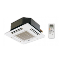
Explanation of buttons and display functions of the wireless remote controller.

Wired Remote Controller (PAR-33MAA) Operation

Detailed explanation of display modes and buttons for the wired remote controller.

Unit Specifications

Indoor Unit Performance Data

Table listing technical specifications for different indoor unit models.

Indoor Unit Wiring Diagram

Refrigerant System Diagram

Troubleshooting - General Overview

Self-Diagnosis Code Summary

Summary of check codes and actions for reoccurring/non-reoccurring issues.

Malfunction Diagnosis via Remote Controller

Procedure for using the remote controller to perform self-diagnosis.

Troubleshooting - Error Codes

Indoor Unit Error Code Details

Table listing check codes, symptoms, and remarks for indoor unit errors.

External Unit Error Code Details

Table listing check codes, symptoms, and remarks for errors detected outside the indoor unit.

Self-Diagnosis Action Table (Codes P1, P2, P4, P5)

Self-Diagnosis Action Table (Codes P5, P6, P8)

Self-Diagnosis Action Table (Codes P9, PL, E0/E4)

Self-Diagnosis Action Table (Codes E3/E5, E6, E7, FB(Fb), E1/E2)

Self-Diagnosis Action Table (Codes PA, PB(Pb))

Troubleshooting Specific Problems

LED2 Off Troubleshooting Procedure

Troubleshooting steps for when LED2 on the indoor controller board is off.

Indoor Controller Board Test Points

Main Parts Troubleshooting Guide

Disassembly Procedures - Initial Access

Disassembly Procedures - Internal Components

Disassembly Procedures - Heat Exchanger Components

Disassembly Procedures - Drain and Heat Exchanger

Related product manuals