EasyManua.ls Logo

Mitsubishi Electric SLZ Series User Manual

Mitsubishi Electric SLZ Series
60 pages
To Next Page IconTo Next Page
Page #1 background imageLoading...
Page #1 background image
TECHNICAL & SERVICE MANUAL
CONTENTS
1. REFERENCE MANUAL
......................
2
2. SAFETY PRECATION .........................2
3. PARTS NAMES AND FUNCTIONS
.....
9
4. SPECIFICATIONS
.............................
10
5. NOISE CRITERION CURVES
...........
10
6. OUTLINES AND DIMENSIONS
.........
12
7. WIRING DIAGRAM
............................
14
8.
REFRIGERANT SYSTEM DIAGRAM
.....
15
9. TROUBLESHOOTING
.......................
16
10. 4-WAY AIRFLOW SYSTEM
...............
29
11. DISASSEMBLY PROCEDURE
..........
31
No. TCH067
Indoor unit
[Model Name] [Service Ref.]
INDOOR UNIT
Model name
indication
September 2021
PARTS CATALOG (TCB067)
SPLIT-TYPE, HEAT PUMP AIR CONDITIONERS
R32/R410A
SLZ-M15FA2.TH
SLZ-M15FA2-ER.TH
SLZ-M15FA2-ET.TH
SLZ-M25FA2.TH
SLZ-M25FA2-ER.TH
SLZ-M25FA2-ET.TH
SLZ-M35FA2.TH
SLZ-M35FA2-ER.TH
SLZ-M35FA2-ET.TH
SLZ-M50FA2.TH
SLZ-M50FA2-ER.TH
SLZ-M50FA2-ET.TH
SLZ-M60FA2.TH
SLZ-M60FA2-ER.TH
SLZ-M60FA2-ET.TH
SLZ-M15FA2.TH
SLZ-M15FA2-ER.TH
SLZ-M15FA2-ET.TH
SLZ-M25FA2.TH
SLZ-M25FA2-ER.TH
SLZ-M25FA2-ET.TH
SLZ-M35FA2.TH
SLZ-M35FA2-ER.TH
SLZ-M35FA2-ET.TH
SLZ-M50FA2.TH
SLZ-M50FA2-ER.TH
SLZ-M50FA2-ET.TH
SLZ-M60FA2.TH
SLZ-M60FA2-ER.TH
SLZ-M60FA2-ET.TH
TCH067.indd 1TCH067.indd 1 29/9/2564 13:36:2829/9/2564 13:36:28
Question and Answer IconNeed help?

Do you have a question about the Mitsubishi Electric SLZ Series and is the answer not in the manual?

Mitsubishi Electric SLZ Series Specifications

General IconGeneral
BrandMitsubishi Electric
ModelSLZ Series
CategoryAir Conditioner
LanguageEnglish

Summary

REFERENCE MANUAL

SAFETY PRECAUTION

MEANINGS OF SYMBOLS DISPLAYED ON THE UNIT

Explains symbols used on the unit for safety warnings and precautions.

ALWAYS OBSERVE FOR SAFETY

General safety guidelines to follow before performing any service or operation.

CAUTIONS RELATED TO NEW REFRIGERANT

Safety precautions specific to handling R32/R410A refrigerants during service.

Cautions for unit using R32 refrigerant

Specific safety measures for units operating with R32 refrigerant.

PARTS NAMES AND FUNCTIONS

INDOOR UNIT

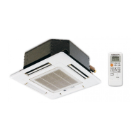
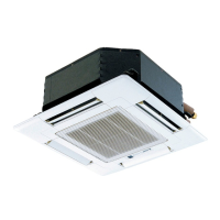
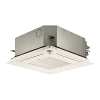
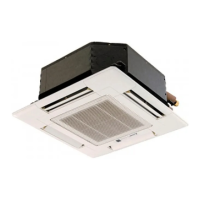
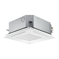
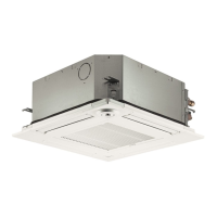
Identifies and describes the components of the indoor unit.

SPECIFICATIONS

NOISE CRITERION CURVES

OUTLINES AND DIMENSIONS

Model Dimensions and Specifications

Provides physical dimensions and key specifications for various indoor unit models.

WIRING DIAGRAM

Model Wiring Diagrams

Illustrates the electrical connections for different indoor unit models.

REFRIGERANT SYSTEM DIAGRAM

Model Refrigerant System Diagrams

Shows the refrigerant circuit layout for various indoor unit models.

TROUBLESHOOTING

9-1. TROUBLESHOOTING

General overview of troubleshooting steps and procedures for common issues.

9-2. MALFUNCTION-DIAGNOSIS METHOD BY REMOTE CONTROLLER

Procedure for diagnosing malfunctions using the remote controller's self-check function.

9-3. SELF-DIAGNOSIS ACTION TABLE

Table detailing error codes, causes, and countermeasures for self-diagnosis.

9-4. TROUBLESHOOTING OF PROBLEMS

Specific troubleshooting steps for various operational problems and symptoms.

9-5. TEST POINT DIAGRAM

Diagram showing test points on the indoor controller board for diagnostics.

9-6. FUNCTION OF DIP SWITCH

Explanation of DIP switch settings for capacity and other functions.

9-7. TROUBLE CRITERION OF MAIN PARTS

Criteria for checking the normal/abnormal status of key components.

4-WAY AIRFLOW SYSTEM

10-1. FRESH AIR INTAKE (LOCATION FOR INSTALLATION)

Guidance on installing fresh air intake ducts and their placement.

10-2. FRESH AIR INTAKE AMOUNT & STATIC PRESSURE CHARACTERISTICS

Data on fresh air intake volume and static pressure characteristics.

10-3. OPERATION IN CONJUNCTION WITH DUCT FAN (BOOSTER FAN)

Instructions for operating the unit with a booster fan.

10-4. FIXING HORIZONTAL VANE

Procedure for adjusting the horizontal vane angle for optimal airflow.

DISASSEMBLY PROCEDURE

REMOTE CONTROLLER AND SERVICE FUNCTIONS

13-1. REMOTE CONTROLLER FUNCTIONS

Overview of functions and buttons for the remote controller.

13-2. ERROR INFORMATION

How to check and interpret error codes displayed on the remote controller.

13-3. SERVICE MENU

Steps to access the service menu, including password entry.

13-4. TEST RUN

Procedure for performing a test run using the remote controller.

13-5. FUNCTION SETTING

How to set various unit functions using the remote controller.

13-6. ROTATION SETTING

Instructions for setting rotation functions via wired remote controller.

13-7. ERROR HISTORY

How to view and delete error logs from the unit.

13-8. SELF-DIAGNOSIS

Steps for performing self-diagnosis using the remote controller.

13-9. REMOTE CONTROLLER CHECK

Procedure to diagnose and check the functionality of the remote controller.

13-10. SMOOTH MAINTENANCE

How to access and utilize the smooth maintenance function.

13-11. REQUEST CODE

How to retrieve operation data using request codes via the remote controller.

Related product manuals