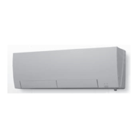
Do you have a question about the Mitsubishi Electric Trane NTXWPH06B112AA and is the answer not in the manual?
Lists all included accessories with their quantities for model setup.
Details the operational voltage, temperature, and humidity limits for the unit.
Provides airflow rates, air speeds, and coverage areas for different operational modes.
Explains how to shorten timer set times for service purposes.
Guides on assigning remote controllers to specific indoor units for exclusive operation.
Details how to set the remote controller based on the indoor unit's installation location.
Describes the automatic restart feature after power interruption and how to disable it.
Explains the layout and functions of the wireless remote controller buttons.
Describes the meaning of the indicator lamps on the indoor unit.
Details the primary modes: Cool, Dry, Fan, Heat, and Auto.
Covers automatic vane operation and vertical vane control for optimal airflow.
Explains setting ON/OFF timers, weekly timers, and managing schedules.
Details i-see control, absence detection, and natural airflow simulation.
Covers INDIRECT/DIRECT, SMART SET, emergency operations, and temp unit changes.
Lists safety and procedural guidelines before starting troubleshooting.
Explains how to retrieve and interpret error codes from the unit's memory.
Provides steps to check the functionality of the i-see sensor and its indicator.
Guides on initial unit checks, general troubleshooting procedures, and flowcharts.
A table correlating indicator patterns with potential faults and remedies.
Provides resistance checks and criteria for diagnosing key components.
Detailed troubleshooting steps for fan motors, controllers, and wiring issues.
Steps to check the remote controller and indoor electronic control P.C. board.
Procedures for checking the indoor P.C. board and fan motor.
Guides on how to diagnose miswiring and serial signal communication errors.
Addresses issues of electromagnetic noise affecting radios and TVs.
Illustrates test points and voltage references on circuit boards for diagnostics.
Step-by-step guide to removing the unit's outer panels.
Instructions for safely removing the electrical box assembly.
Details on removing various P.C. boards like power, control, and receiver boards.
Procedures for removing the air outlet nozzle and vane motor units.
Steps to extract the indoor fan motor, coil thermistors, and line flow fan.
| Category | Air Conditioner |
|---|---|
| Model | NTXWPH06B112AA |
| SEER Rating | 20.5 |
| Phase | 1 |
| HSPF Rating | 10.0 |
| Operating Temperature (Cooling) | 5°F to 115°F |


 Loading...