EasyManua.ls Logo

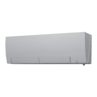
Mitsubishi Electric TRANE NTXWST09A112AA User Manual

Mitsubishi Electric TRANE NTXWST09A112AA
52 pages
To Next Page IconTo Next Page
Page #1 background imageLoading...
Page #1 background image
CONTENTS
1. TECHNICAL CHANGES
·······································
2
2. PART NAMES AND FUNCTIONS ····················· 3
3. SPECIFICATION ················································ 6
4. OUTLINES AND DIMENSIONS ························ 8
5. WIRING DIAGRAM ·········································· 10
6. REFRIGERANT SYSTEM DIAGRAM ············· 12
7. SERVICE FUNCTIONS ··································· 13
8. MICROPROCESSOR CONTROL ··················· 15
9. TROUBLESHOOTING ····································· 23
10. DISASSEMBLY INSTRUCTIONS ···················· 41
Outdoor unit service manual
NTXSSTA112AA, NTYSSTA112AA Series (OBHT733)
NTXMMX•A•AA, NTXMPH•A•AA
Series (OCHT573)
PARTS CATALOG (OBBT732)
NTXWST18A112AA
NTYWST18A112AA
INDOOR UNIT
SERVICE MANUAL
INDOOR UNIT
Models
NTXWST06A112AA
NTXWST09A112AA NTYWST09A112AA
NTXWST12A112AA NTYWST12A112AA
NTXWST15A112AA NTYWST15A112AA
NTXWST18A112AA NTYWST18A112AA
NTXWST24A112AA NTYWST24A112AA
No. OBHT732
Question and Answer IconNeed help?

Do you have a question about the Mitsubishi Electric TRANE NTXWST09A112AA and is the answer not in the manual?

Mitsubishi Electric TRANE NTXWST09A112AA Specifications

General IconGeneral
BrandMitsubishi Electric
ModelTRANE NTXWST09A112AA
CategoryAir Conditioner
LanguageEnglish

Summary

TECHNICAL CHANGES

SPECIFICATION

WIRING DIAGRAM

REFRIGERANT SYSTEM DIAGRAM

SERVICE FUNCTIONS

MICROPROCESSOR CONTROL

WIRELESS REMOTE CONTROLLER

Explains the functions and buttons of the remote controller.

8-10. EMERGENCY/TEST OPERATION

Details emergency and test run operations.

TROUBLESHOOTING

9-1. CAUTIONS ON TROUBLESHOOTING

Lists safety precautions before troubleshooting.

9-4. TROUBLESHOOTING CHECK TABLE

Lists symptoms, conditions, and remedies for abnormalities.

9-5. TROUBLE CRITERION OF MAIN PARTS

Details resistance checks for major components.

9-6. TROUBLESHOOTING FLOW

Provides flowcharts for specific troubleshooting scenarios.

B Check of remote controller and indoor electronic control P.C. board

Guides on checking remote and indoor control board issues.

C Check of indoor P.C. board and indoor fan motor

Guides on checking indoor P.C. boards and fan motors.

D How to check miswiring and serial signal error

Explains how to diagnose wiring and communication errors.

9-7. TEST POINT DIAGRAM AND VOLTAGE

Provides electrical test points and voltage references.

DISASSEMBLY INSTRUCTIONS

Related product manuals