EasyManua.ls Logo

Mitsubishi Electric TRANE TPKA0A0121HA70A User Manual

Mitsubishi Electric TRANE TPKA0A0121HA70A
40 pages
To Next Page IconTo Next Page
Page #1 background imageLoading...
Page #1 background image
SERVICE MANUAL
TPKA0A0121HA70A
TPKA0A0181HA70A
Indoor unit
[Model Name]
September 2019
No. OCHT637
CONTENTS
1. REFERENCE MANUAL
...................................
2
2. SAFETY PRECAUTION
...................................
3
3. PARTS NAMES AND FUNCTIONS
.................
4
4. SPECIFICATIONS
...........................................
12
5. NOISE CRITERION CURVES
.........................
13
6. OUTLINES AND DIMENSIONS
......................
14
7. WIRING DIAGRAM
.........................................
15
8. REFRIGERANT SYSTEM DIAGRAM
............
16
9. TROUBLESHOOTING
....................................
17
10. FUNCTION SETTING
.....................................
31
11. SPECIAL FUNCTION
.....................................
32
12. DISASSEMBLY PROCEDURE
.......................
36
PARTS CATALOG (OCBT637)
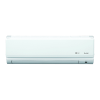
INDOOR UNIT
WIRED REMOTE
CONTROLLER
(Option)
IR WIRELESS REMOTE
CONTROLLER (Option)
ON/OFF
TEMP.
COOL
DRY
AUTO
FAN
HEAT
MENU
ON
OFF
RETURN
SELECT
HOLD
Question and Answer IconNeed help?

Do you have a question about the Mitsubishi Electric TRANE TPKA0A0121HA70A and is the answer not in the manual?

Mitsubishi Electric TRANE TPKA0A0121HA70A Specifications

General IconGeneral
BrandMitsubishi Electric
ModelTRANE TPKA0A0121HA70A
CategoryHeat Pump
LanguageEnglish

Summary

REFERENCE MANUAL

OUTDOOR UNIT SERVICE MANUAL

Lists outdoor unit models and their corresponding service manuals.

Remote controller (Optional parts)

Details of wired and IR wireless remote controllers.

SAFETY PRECAUTION

ALWAYS OBSERVE FOR SAFETY

General safety guidelines for servicing the unit.

CAUTIONS RELATED TO NEW REFRIGERANT

Specific safety warnings for R410A refrigerant.

PARTS NAMES AND FUNCTIONS

Indoor unit

Identifies and describes components of the indoor unit.

Wired Remote Controller <TAR-40MAA>

Explains the interface and buttons of the wired remote controller.

IR wireless remote controller (Option)

Explains the interface and buttons of the IR wireless remote controller.

SPECIFICATIONS

NOISE CRITERION CURVES

OUTLINES AND DIMENSIONS

WIRING DIAGRAM

REFRIGERANT SYSTEM DIAGRAM

TROUBLESHOOTING

TROUBLESHOOTING

Summarizes check codes and actions for recurring and non-recurring troubles.

MALFUNCTION-DIAGNOSIS METHOD BY REMOTE CONTROLLER

Explains how to diagnose malfunctions using the remote controller.

SELF-DIAGNOSIS ACTION TABLE

Provides a table of check codes, causes, and countermeasures.

TROUBLESHOOTING BY INFERIOR PHENOMENA

Addresses issues related to vane performance and IR receiver problems.

EMERGENCY OPERATION

Details how to perform emergency operation when controllers fail.

HOW TO CHECK THE PARTS

Provides methods to check specific components like thermistors and motors.

DC Fan motor (fan motor/indoor controller circuit board)

Details the procedure for checking the DC fan motor.

TEST POINT DIAGRAM

Illustrates test points on the indoor controller board for diagnostics.

FUNCTIONS OF DIP SWITCH AND JUMPER WIRE

Explains the function of DIP switches and jumper wires on the controller board.

FUNCTION SETTING

UNIT FUNCTION SETTING BY THE REMOTE CONTROLLER

Describes how to set unit functions using the remote controller.

SPECIAL FUNCTION

Rotation Function (and back-up function, 2nd stage cut-in function)

Details rotation and back-up functions for multiple units.

How to set rotation function (Back-up function, 2nd stage cut-in function)

Explains the procedure for setting rotation and back-up functions.

BACK-UP HEATING FUNCTION

Details the operation and settings for the back-up heating function.

DISASSEMBLY PROCEDURE

Removing the lower side of the indoor unit from the installation plate

Step-by-step guide to detach the lower unit from the installation plate.

Removing the front panel

Instructions for safely removing the front panel of the indoor unit.

Removing the indoor controller board and IR wireless controller board

Detailed steps to remove the controller boards.

Removing the electrical box

Steps for safely removing the electrical box.

Removing the nozzle assembly (with vane and vane motor) and drain hose

Guide to remove the nozzle assembly and drain hose.

Removing the indoor fan motor and the line flow fan

Steps to remove the fan motor and line flow fan.

Removing the vane motor

Instructions for removing the vane motor unit.

Removing the heat exchanger

Guide to remove the heat exchanger.

Removing the room temperature thermistor

Instructions for removing the room temperature thermistor.

Related product manuals