EasyManua.ls Logo

Mitsubishi Electric TRANE TPKA0A0181HA70A User Manual

Mitsubishi Electric TRANE TPKA0A0181HA70A
40 pages
To Next Page IconTo Next Page
Page #1 background imageLoading...
Page #1 background image
SERVICE MANUAL
TPKA0A0121HA70A
TPKA0A0181HA70A
Indoor unit
[Model Name]
September 2019
No. OCHT637
CONTENTS
1. REFERENCE MANUAL
...................................
2
2. SAFETY PRECAUTION
...................................
3
3. PARTS NAMES AND FUNCTIONS
.................
4
4. SPECIFICATIONS
...........................................
12
5. NOISE CRITERION CURVES
.........................
13
6. OUTLINES AND DIMENSIONS
......................
14
7. WIRING DIAGRAM
.........................................
15
8. REFRIGERANT SYSTEM DIAGRAM
............
16
9. TROUBLESHOOTING
....................................
17
10. FUNCTION SETTING
.....................................
31
11. SPECIAL FUNCTION
.....................................
32
12. DISASSEMBLY PROCEDURE
.......................
36
PARTS CATALOG (OCBT637)
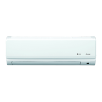
INDOOR UNIT
WIRED REMOTE
CONTROLLER
(Option)
IR WIRELESS REMOTE
CONTROLLER (Option)
ON/OFF
TEMP.
COOL
DRY
AUTO
FAN
HEAT
MENU
ON
OFF
RETURN
SELECT
HOLD
Question and Answer IconNeed help?

Do you have a question about the Mitsubishi Electric TRANE TPKA0A0181HA70A and is the answer not in the manual?

Mitsubishi Electric TRANE TPKA0A0181HA70A Specifications

General IconGeneral
BrandMitsubishi Electric
ModelTRANE TPKA0A0181HA70A
CategoryHeat Pump
LanguageEnglish

Summary

SERVICE MANUAL

Model Identification

Identifies the specific indoor unit models covered by the manual.

2. SAFETY PRECAUTION

R410A Refrigerant Cautions

Cautions for units utilizing R410A refrigerant.

4. SPECIFICATIONS

6. OUTLINES AND DIMENSIONS

7. WIRING DIAGRAM

8. REFRIGERANT SYSTEM DIAGRAM

9. TROUBLESHOOTING

Summary of Self-Diagnosis Actions

Summarizes self-diagnosis check codes and actions for reoccurring/non-reoccurring troubles.

9-2. Malfunction Diagnosis Method

IR Wireless Remote Controller Diagnosis

Details the procedure for diagnosing malfunctions using the IR wireless remote controller.

Troubleshooting: Check Code Patterns

Indoor Unit Errors (Output Pattern A)

Lists symptoms, check codes, and remarks for indoor unit errors.

Troubleshooting: Other Unit Error Patterns

Outdoor Unit Errors (Output Pattern B)

Lists symptoms, check codes, and remarks for errors detected by outdoor units.

9-3. SELF-DIAGNOSIS ACTION TABLE

P1 Room Temperature Thermistor Error

Details the cause and countermeasure for P1 error related to room temperature thermistor.

Self-Diagnosis Table: Protection Errors

P6 Freezing/Overheating Protection

Explains causes and countermeasures for P6 errors related to protection functions.

Self-Diagnosis Table: Thermistor Errors

P9 Condenser/Evaporator Thermistor Error

Details causes and countermeasures for P9 error related to condenser/evaporator thermistor.

Self-Diagnosis Table: Controller Errors

E3/E5 Remote Controller Transmission Error

Covers causes and countermeasures for remote controller transmission errors (E3/E5).

9-4. Troubleshooting by Inferior Phenomena

Vane Performance Failure

Addresses issues with vane movement and potential causes/solutions.
9-5. EMERGENCY OPERATION

9-6. How to Check Parts

9-6-2. DC Fan Motor Check

9-7. Test Point Diagram

How to Send a Request Code

12. DISASSEMBLY PROCEDURE

Controller Board Removal

Related product manuals