'15 • HM-T-246
-
-
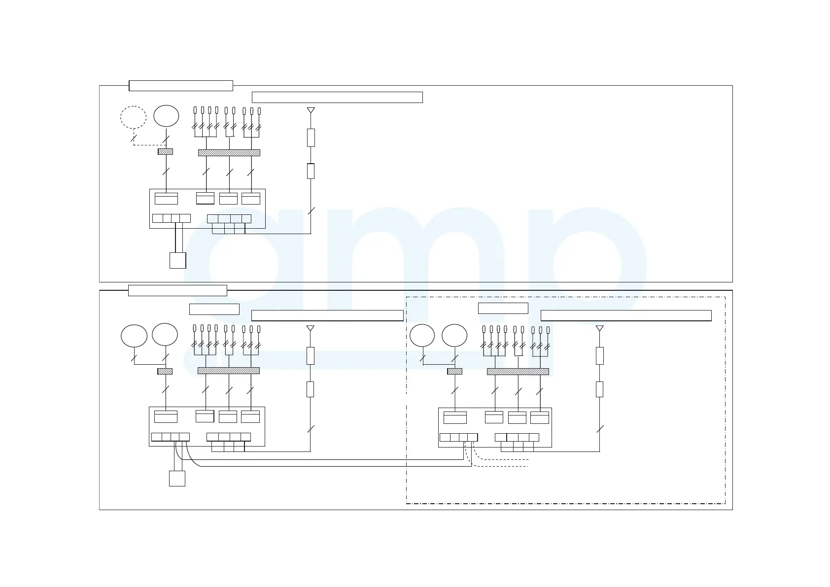
*1In case of multiple master unit connected to a remote controlindividually,
CWFV5 is required for each master unit.
*2 If another master unit without remote control is connected in
the same system, the same wiring method as this should be done.
(16 sets of master units are connectable at the maximum.)
TB
T PUMP WATER HEATER
TB2
TB1
5
3
CWFV3
64
8
TB
4
Earth leakage breaker
(Impulse withstanding)
Circuit breaker
Power source: 3 phase 380/400/415V±5% 50/60Hz
TB
5
3
CWFV3
64
8
TB
4
Earth leakage breaker
(Impulse withstanding)
Circuit breaker
Power source: 3 phase 380/400/415V±5% 50/60Hz
TB
CWFV
T1-4
T5-6 T7-9
TB2
TB1
Connector
5
3
CWFV3
64
8
TB
4
Earth leakage breaker
(Impulse withstanding)
Circuit breaker
Power source: 3 phase 380/400/415V±5% 50/60Hz
Master unit 1
Master unit 2
CWFV5 CWFV5
3
3
CWFV5
3
*1
*2
CWFV
T1-4
T5-6 T7-9
ABXY
L1 L2 L3 N
R
Connector
Terminal
Terminal
CWFV
T1-4
T5-6 T7-9
R
Connector
ABXY
L1 L2 L3 N
ABXY
L1 L3 NL2
TB2
TB1
In case of Master unit 1 and
2
In case of Master unit only
HEA
T PUMP WATER HEATER
HEAT PUMP WATER HEATER
6-1 Wiring system diagram
www.ampair.co.uk | sales@ampair.co.uk
 Loading...