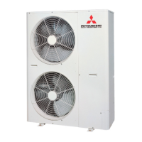
Do you have a question about the Mitsubishi Heavy Industries FDC224KXE6 and is the answer not in the manual?
| Brand | Mitsubishi Heavy Industries |
|---|---|
| Model | FDC224KXE6 |
| Cooling Capacity | 22.4 kW |
| Heating Capacity | 25.0 kW |
| Power Supply | 3 Phase, 380-415V, 50Hz |
| Refrigerant | R410A |
| Type | Split System |
Explains the display items and buttons of the wired remote controller with the cover opened.
Details functional item operations for compressor, fans, valves across cooling and heating modes.
Explains dehumidifying control logic, including sensor and thermistor inputs for temperature management.
Describes ON timer, OFF timer, and weekly timer settings, including combinations and operation.
Explains how to activate the CPU reset function by pressing specific buttons simultaneously.
Details how the unit resumes operation after power failure by storing and recalling settings.
Outlines the operation of major functional components under different operation modes.
Details compressor control including 4-way valve switching safeguard and protection start.
Explains outdoor fan speed control based on high pressure and outdoor air temperature.
Explains defrost control conditions based on temperature and operation time.
Details various protective controls like discharge pipe temperature and over-current.
Explains how to start and end test run operations for cooling and heating.
Lists optional controls and functions selectable via PCB connectors.
Explains operation permission/prohibition modes and demand control settings.
Explains start conditions, control contents, and end conditions for 2-step demand control.
Details start conditions, control contents, and end conditions for silent mode operation.
Explains how to enable/disable and set outdoor fan snow protection control.
Describes how to use external output functions for optional devices via relay outputs.
Explains how energy saving mode controls compressor upper limit speed based on settings.
Details how to forcibly determine indoor unit operation mode (cooling/heating) using PCB switches.
Describes how the system responds to emergency stop signals from optional devices.
Explains the pump down control procedure for refrigerant recovery during unit removal.
Provides a basic procedure for troubleshooting by connecting to a Mente PC and analyzing error data.
Explains troubleshooting steps for specific errors like E41, E42, E45, and E48.
Lists indoor and outdoor unit inspection displays, error codes, classifications, and pages.
Provides wiring diagrams for outdoor units of various models.
Details wiring diagrams for different types of indoor units.
Explains refrigerant piping configurations for various indoor unit types.
Provides critical safety precautions for installation work, categorized by risk level.
Details indoor unit installation procedures, including preparation and mounting.
Explains the work procedure for connecting refrigerant pipes, including flare nut tightening.
Provides instructions for installing the drain pipe, including slope and insulation.
Details electrical wiring work procedures and connection methods.
Provides instructions for attaching the panel after electrical wiring work.
Lists items to check after all installation work is completed for proper functionality.
Step-by-step instructions for opening the remote controller and embedding the cord.
Details initial checks and preparation before starting outdoor unit installation.
Guides selection of optimal installation locations for outdoor units based on environmental factors.
Provides instructions for preparing suspension bolts and wall installation bolts.
Explains the procedure for connecting refrigerant pipes, including flare nut tightening.
Details the installation of the drain pipe, ensuring proper slope and insulation.
Covers electrical installation work and wiring connections for outdoor units.
Lists items to check after outdoor unit installation is completed.
Illustrates wiring diagrams for power source, circuit breakers, and signal lines.
Explains connection procedures for power supply and signal cables, including precautions.
Explains connection methods for Superlink/conventional communication protocols.
Details manual and automatic address setting procedures for indoor and outdoor units.
Explains how to set various functions using the remote controller.
Lists checks to perform before starting operation, including safety and grounding.
Explains how to perform test runs for cooling, heating, and drain pump operations.
Details instructions for installing branch pipe sets, including size selection and procedures.
 Loading...