-
112
-
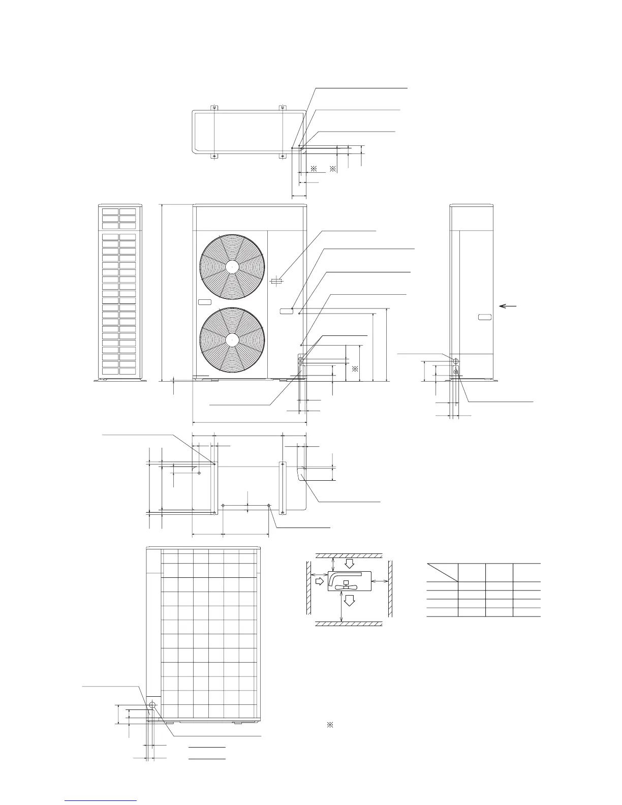
Model FDCVA1002HESAR
Unit: mm
Minimum allowable space to the obstacles
L1
L2
L3
Air outlet
Air inlet
Air inlet
Maintenance
space
L4
Mark
Installation
type
Unit : mm
L2
L3
L4
L1
300
150
5
Open
Open
Open
I
5
300
5
II
150
5
500
III
( )
1505
10
55
1550
970
50
619
576
306
155
85
35
69
60
120
48
52
27 50
170
50 85
50
15 50
50
160
70
370
410 2020
40 40
55
60
262 388
38
580190 200
103 15
60 15
60
44
Terminal block
Liquid piping : φ9.52(3/8")
(Flare connecting)
Gas piping : φ19.05(3/4")
(Flare connecting)
Gas piping : φ25.4(1")
(Brazing connecting)
Liquid piping : φ9.52(3/8")
(Flare connecting)
Gas piping : φ19.05(3/4")
(Flare connecting)
Gas piping : φ25.4(1")
(Brazing connecting)
Opening for
electric wiring
Opening for piping
and electric wiring
Opening for piping
and electric wiring
Opening for piping
and electric wiring
Opening for piping
and electric wiring
Opening for
electric wiring
Holes for anchor bolt
Holes for drain
Opening for electric wiring
VIEW A
A
(M10 × 4 pcs.)
45
Notes
(1) It is prohibited to install in a space enclosed with walls at four sides.
(2) Unit must be secured with anchor bolts.
Anchor bolt should not protrude more than 15 mm above the surface.
(3) Where strong winds blow, the blow outlet must be oriented at right angle against the
wind direction.
(4) Secure a space of 1 m or more above the unit.
(5) Barrier standing in front of the blow outlet must be lower than the height of unit.
(6) Use the attached accessory piping for connection as the gas piping φ25.4(1″), and
connect it with the field piping.
(7) The
dimensions show the connecting position of the φ25.4(1″) accessory piping
for connection.
 Loading...