-
89
-
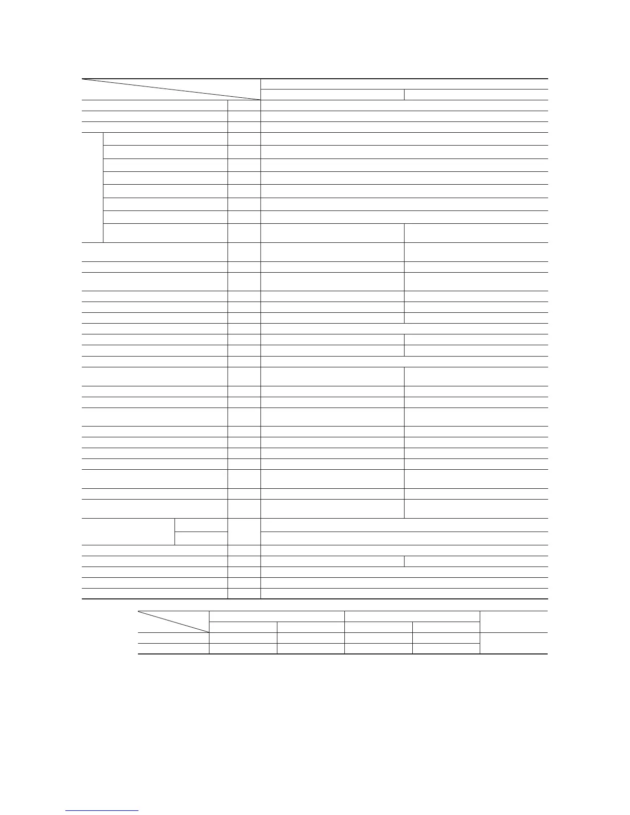
Model FDKNVA602HES T2R (Indoor unit: 3 units, Outdoor unit: 1 unit)
Model
Item
FDKNVA602HEST2R
FDKNA201R FDCVA602HESAR
Nominal cooling capacity
(1)
kW
14.0 [6.5~14.5]
Nominal heating capacity
(1)
kW
16.0 [6.3~16.5]
Power source 3 Phase, 380–415V 50Hz/380V 60Hz
Operation data
(3)
Cooling power consumption kW
4.82/4.82
Running current (Cooling) A
7.0/7.4
Power factor (Cooling) %
99/99
Heating power consumption kW
4.79/4.79
Running current (Heating) A
7.0/7.4
Power factor (Heating) %
99/98
Inrush current (L.R.A) A
5
Noise level dB(A)
Powerful mode Hi:47 Me:44 Lo:41
Mild mode Hi:44 Me:41 Lo:38
53
Exterior dimensions
Height × Width × Depth
mm 298 × 840 × 240 845 × 970 × 370
Net weight kg 12 74
Refrigerant equipment
Compressor type & Q’ty
–
RM-B5125MDE31 × 1
Starting method – Direct line start
Heat exchanger
Slitted fin & inner grooved tubing Straight fin & inner grooved tubing
Refrigerant control – Electronic expansion valve
Refrigerant R410A
Quantity kg
–
3.8 [Pre-charged up to the piping length of 30m]
Refrigerant oil
r
–
0.7 (M-MA68)
Defrost control Microcomputer controlled de-icer
Air handling equipment
Fan type & Q’ty
Tangential fan × 1 Propeller fan × 1
Motor W 33 × 1 12.0 × 1
Starting method Direct line start Direct line start
Air fl ow CMM
Powerful mode Hi:13 Me:12 Lo:11
Mild mode Hi:12 Me:11 Lo:9
Cooling:75, Heating:73
Outside air intake
Unavailable –
Air filter, Q’ty Plastic net (washable) × 2 –
Shock & vibration absorber Rubber sleeve (for fan motor) Rubber mount (for compressor)
Electric heater W – 20 (Crank case heater)
Operation control
Operation switch
Wireless remote control switch
(Optional : RCN-E1R)
Wired remote control switch (Optional : RC-E
1
R)
– (Indoor unit side)
Room temperature control Thermostat by electronics –
Safety equipment
Internal thermostat for fan motor.
Frost protection thermostat.
Internal thermostat for fan motor.
Anomalous discharge temperature protection.
Installation data
Refrigerant piping size
Liquid line
mm
(in)
Indoor branch pipe, Outdoor main pipe: φ9.52 (3/8″)
Gas line Indoor branch pipe: φ12.7 (1/2″), Outdoor main pipe: φ15.88 (5/8″)
Connecting method Flare piping
Drain hose
Connectable with VP16 (I.D. 16mm, O.D. 22mm) –
Insulation for piping Necessary (both Liquid & Gas lines)
Accessories Mounting kit. Drain hose
Optional parts –
Notes (1) The data are measured at the following conditions.
Item
Operation
Indoor air temperature Outdoor air temperature
Standards
DB WB DB WB
Cooling 27˚C 19˚C 35˚C 24˚C
ISO-T1
Heating 20˚C – 7˚C 6˚C
(2) This packaged air-conditioner is manufactured and tested in conformity with the following standard. ISO-T1 “UNITARY AIR-CONDITIONERS”
(3) The operation data indicate when the air-conditioner is operated at 400V 50Hz or 380V 60Hz.
(4) Values in [ ~ ] show the minimum to maximum range.
(5) Indoor unit specifications show the specifications for one unit. Capacity and running characteristics values are shown for the case where three indoor
units are combined and run together.
(6) If wireless specifications are used, use 1 wireless indoor unit in combination with wired indoor units.
 Loading...