Do you have a question about the Mitsubishi Heavy Industries SRC50ZFX-S and is the answer not in the manual?
| Cooling Capacity | 5.0 kW |
|---|---|
| Heating Capacity | 6.0 kW |
| Power Supply | 220-240V, 50Hz |
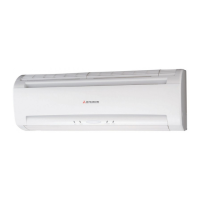
| Indoor Unit Dimensions (W x H x D) | 920 x 305 x 230 mm |
| Outdoor Unit Dimensions (W x H x D) | 780 x 540 x 290 mm |
| Type | Split System |
| Noise Level (Outdoor Unit) | 50 dB |
Technical specifications for SRK20ZFX-S (Indoor/Outdoor) units.
Explains how to correct capacity based on temperature and piping length.
Shows the electrical wiring diagram for SRK20ZFX-S, 25ZFX-S, 35ZFX-S models.
Explains the functions of buttons on the wireless remote control.
Details protection against compressor overheating.
Critical safety warnings related to installation, electrical work, and refrigerant handling.
Important precautions regarding grounding, electrical shock, and environmental hazards.
Guidance on selecting suitable locations for indoor units for airflow and servicing.
Guidance on selecting suitable locations for outdoor units for circulation and noise.
Instructions for connecting indoor and outdoor unit wiring.
Details on connecting refrigerant piping using torque wrench.
Procedures for air purging and vacuum operation.
Steps for conducting a test run and checks.
Guides on troubleshooting electrical issues.
Step-by-step guide for when the unit does not run.
Step-by-step guide for when the unit is running but malfunctioning.
Table detailing error codes and their causes/displays.
Explains how to access and use the service mode.
Details the service mode display procedure.
Explains self-diagnosis data and stop data.
Troubleshooting steps for sensor errors.
Troubleshooting steps for current cut errors.
Troubleshooting steps for compressor overheating.
Troubleshooting steps for signal transmission errors.
Troubleshooting steps for outdoor unit issues.
Troubleshooting steps for indoor fan motor errors.
Troubleshooting steps for outdoor fan motor errors.
Details on R410A adoption, chemical characteristics, and pressure.
Safety precautions for R410A installation and servicing.
Information on copper pipes and joints for R410A.
Lists tools exclusive for R410A and general tools.
Procedures for air purging and leak checking.
Steps for additional refrigerant charging based on piping length.
General procedures for refrigerant recovery.