Do you have a question about the Mitsubishi Heavy Industries SRC63ZR-S and is the answer not in the manual?
| Cooling Capacity | 6.3 kW |
|---|---|
| Heating Capacity | 7.1 kW |
| Power Supply | 220-240V, 50Hz |
| Indoor Unit Dimensions (WxHxD) | 920 x 305 x 230 mm |
| Outdoor Unit Dimensions (WxHxD) | 780 x 540 x 290 mm |
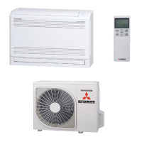
| Type | Split System |
| Seasonal Energy Efficiency Ratio (SEER) | 6.10 |
Wiring diagram and component identification for the indoor unit.
Wiring diagram and component identification for the outdoor unit.
Safety precautions for installing the outdoor unit.
General safety warnings and precautions for installation work.
Overview of remote control functions and operation modes.
Component operation during heating mode and failure conditions.
Component operation during cooling mode and failure conditions.
Automatic mode selection based on temperature sensors.
Important safety precautions before performing maintenance or checks.
Step-by-step guide for diagnosing units that do not operate at all.
Troubleshooting steps for units that are running but have issues.
Table correlating flashing lights with error codes and causes.
Accessing and understanding service data for diagnostics.
Detailed list of error codes, causes, and occurrence conditions.
Procedures for checking sensor errors and related components.
Procedure to check the indoor PCB for proper operation.