Do you have a question about the Mitsubishi Heavy Industries SRC25MA-S and is the answer not in the manual?
| Cooling Capacity | 2.5 kW |
|---|---|
| Heating Capacity | 3.2 kW |
| Power Supply | 220-240V, 50Hz |
| Refrigerant | R32 |
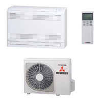
| Type | Split System |
| Noise Level (Indoor Unit) | 21 dB |
| Noise Level (Outdoor Unit) | 49 dB |
Details inverter, fuzzy control, comfort modes, humanization, life, and self-diagnosis.
Explains how to identify the model number and its components.
Lists detailed specifications for various indoor/outdoor units (SRK20MA-S, SRC20MA-S, etc.).
Specifies operating conditions, limits, and provides dimensional drawings for the indoor unit.
Presents circuit diagrams for indoor and outdoor units.
Identifies and describes the function of various parts of the indoor and outdoor units.
Covers emergency switch, auto restart, key lock, and CLEAN operation.
Explains SLEEP operation and setting the timer for unit turn-off.
Details setting ON timers and programmed ON/OFF timers.
Covers current time setting, HI POWER, and JET operations.
Explains POWER SAVE mode and air direction regulation.
Details area setting, installation location, and auto operation logic.
Explains the drying and defrosting operation cycles and conditions.
Covers flap control, EEV control, compressor control, and outdoor fan control.
Explains the speed settings and control of the indoor fan.
Guides on choosing suitable indoor and outdoor unit installation locations.
Step-by-step guides for indoor/outdoor unit installation and pipe connection.
Outlines a systematic method for diagnosing electrical part failures.
Explains using service mode for failure reading and self-diagnosis indications.
Provides comprehensive lists of error/stop codes, causes, and conditions.
Provides troubleshooting steps for various sensor failures.
Troubleshooting for outdoor unit errors, compressor overheat, and power cut.
Troubleshooting for serial transmission, fan motor, and compressor lock errors.
Guides on checking indoor electrical components and fan motor.
Step-by-step guide to diagnose remote controller issues.
Provides circuit diagrams and checks for outdoor unit and inverter.
Procedures for checking the EEV and outdoor fan motor.
Details servicing steps like evacuation, refrigerant charging, and recovery.
Details on using R410A, its properties, and safety.
Safety precautions for installation and servicing with R410A.
Covers materials, joints, and procedures for mounting refrigerant pipes.
Precautions for handling piping materials and procedures for welding.
Details flaring procedures and tool applicability for R410A/R22.
Guides for new installation, removal, replacement, and refitting.
Procedures for recharging refrigerant and recovering refrigerant.
Steps for checking and preparing the recovery procedure.
Lists accessories and tools needed for R410A recovery.
Parts lists and diagrams for indoor unit panel/fan and heat exchanger/control assemblies.
Exploded views and parts lists for outdoor units.
Parts lists and diagrams for outdoor unit panel/fan and heat exchanger/control assemblies.