Do you have a question about the Mitsubishi Heavy Industries SRK25MA-S and is the answer not in the manual?
| Type | Split System |
|---|---|
| Cooling Capacity | 2.5 kW |
| Heating Capacity | 3.2 kW |
| Energy Efficiency Ratio (EER) | 3.21 |
| Coefficient of Performance (COP) | 3.61 |
| Power Supply | 220-240 V, 50 Hz |
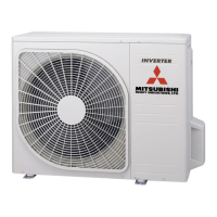
| Outdoor Unit Dimensions (W x H x D) | 780 x 540 x 290 mm |
| Weight (Outdoor Unit) | 30 kg |
| Refrigerant | R410A |
| Noise Level (Outdoor) | 50 dB(A) |
Details inverter, fuzzy control, comfort modes, and humanization features.
Explains the structure of the model number for identification.
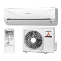
Provides specifications for the SRK20MA-S indoor and SRC20MA-S outdoor units.
Specifies the operating temperature and humidity ranges for cooling and heating.
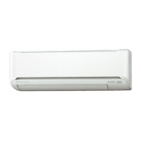
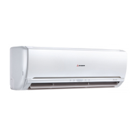
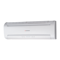
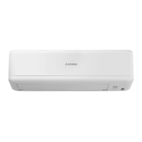
Shows dimensional drawings of the indoor unit (MA-S Series).
Illustrates the refrigerant flow and components in the cooling cycle.
Details capacity correction factors based on temperature, piping length, and frosting.
Electrical circuit diagram for the 20, 25, and 35MA-S models.
Electrical circuit diagram for the 50MA-S model.
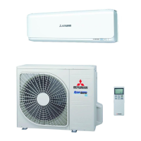
Identifies and labels the components of the indoor and outdoor units and accessories.
Explains the use of the ON/OFF button for emergency operation.
Describes the function of automatic restart after a power interruption.
Explains the key lock function to prevent accidental operation.
Details the CLEAN operation for drying the indoor unit and preventing mold.
Describes the SLEEP mode for maintaining comfortable temperatures automatically.
Explains how to set the timer to turn off the air conditioner automatically.
Explains how to set the timer to turn on the air conditioner automatically.
Describes how to set a programmed timer for automatic ON/OFF cycles.
Details how to set the current time on the remote controller.
Explains the HI POWER mode for rapid cooling or heating.
Describes the JET operation for maximum fan speed cooling or heating.
Explains the POWER SAVE mode for energy efficiency.
Details how to adjust the vertical and horizontal flaps for air direction.
Explains the function to regulate indoor air distribution within specific areas.
Describes how to set the installation location to optimize airflow.
Explains how the system automatically selects operating modes like cooling, heating, or drying.
Details how the drying operation determines and adjusts its state based on temperatures.
Explains the conditions and procedures for the defrosting operation.
Describes the control of vertical and horizontal flaps for various operations.
Explains the various control methods for the electronic expansion valve.
Details the control logic for the compressor's ON/OFF and speed.
Describes the control of the outdoor fan's rotate speed based on various conditions.
Explains the control of the indoor fan's rotate speed and priority.
Provides critical safety warnings and precautions for the installation process.
Guides on selecting appropriate indoor and outdoor unit installation locations.
Details the process of installing the indoor unit, including mounting plate and panel removal.
Outlines the steps for installing the outdoor unit securely.
Explains the preparation and process for connecting refrigerant pipes.
Lists important precautions for using the wireless remote controller.
Provides standard running data for different models under specified conditions.
Outlines precautions and procedures for diagnosing electrical component failures.
Explains how to use the service mode to read past error indications and protection stops.
Provides an overview of R410A refrigerant and its properties.
Details the chemical properties and composition of R410A refrigerant.
Outlines safety precautions for installing and servicing R410A systems.
Covers the selection and mounting of copper pipes and joints for refrigerant piping.
Details the new installation process including vacuum pump usage and refrigerant charging.
Explains the procedure for removing the equipment and its components.
Advises on replacing equipment with new refrigerant piping to avoid issues.
Warns against charging R22 units with R410A refrigerant.
Provides steps for recharging refrigerant during servicing.
Outlines the general procedure for recovering refrigerant.
Lists parts for the SRK20MA-S indoor unit's panel and fan assembly.
Lists parts for the SRC20MA-S outdoor unit's panel and fan assembly.
Lists parts for the SRC25MA-S outdoor unit's panel and fan assembly.
Lists parts for the SRC35MA-S outdoor unit's panel and fan assembly.
Lists parts for the SRC50MA-S outdoor unit's panel and fan assembly.