Do you have a question about the Mitsubishi Heavy Industries SRK50MA-S and is the answer not in the manual?
| Brand | Mitsubishi Heavy Industries |
|---|---|
| Model | SRK50MA-S |
| Category | Air Conditioner |
| Language | English |
Details inverter operation, fuzzy control, comfort modes, humanization, and life expectancy of the air conditioner.
Explains the error codes indicated by the indoor and outdoor sensors and their meanings.
Provides an example and explanation for identifying the air conditioner model number.
Detailed specifications for the SRK20MA-S indoor and SRC20MA-S outdoor units.
Detailed specifications for the SRK25MA-S indoor and SRC25MA-S outdoor units.
Detailed specifications for the SRK35MA-S indoor and SRC35MA-S outdoor units.
Detailed specifications for the SRK50MA-S indoor and SRC50MA-S outdoor units.
Specifies the operating temperature and humidity ranges for the air conditioners.
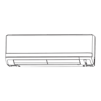
Provides dimensional drawings for the indoor and outdoor units of the air conditioner.
Provides dimensional drawings for the outdoor units of the SRC20, 25, and 35MA-S models.
Provides dimensional drawings for the outdoor unit of the SRC50MA-S model.
Illustrates the refrigerant flow and components in the cooling cycle of the air conditioner.
Details correction factors for temperature, piping length, and frosting for cooling/heating capacity.
Demonstrates how to calculate actual cooling and heating capacity using correction factors.
Presents the electrical circuit diagram for the 20, 25, and 35MA-S models of the air conditioner.
Presents the electrical circuit diagram for the 50MA-S model of the air conditioner.
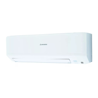
Illustrates and names the various components of the indoor unit.
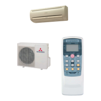
Shows the outdoor unit components and common accessories like remote control and filters.
Explains the function of each button on the remote control for operating the air conditioner.
Describes the indicators and symbols displayed on the remote control for various modes and settings.
Explains how the remote control signals are transmitted to the air conditioner unit.
Explains the function of the emergency ON/OFF switch on the air conditioner unit.
Describes the automatic restart feature that restores operation after a power outage.
Details the key lock function on the remote controller to prevent accidental operation.
Explains the CLEAN operation mode for drying the indoor unit and preventing mold growth.
Describes the SLEEP mode for regulating temperature and ensuring comfort during sleep.
Explains how to set the timer to automatically turn off the air conditioner.
Explains how to set the timer to automatically turn on the air conditioner.
Details how to set combined ON and OFF timer operations for automatic daily operation.
Instructions on setting the current time on the remote controller for timer functions.
Describes the HI POWER mode for rapid cooling or heating for 15 minutes.
Explains the JET operation mode for maximum fan speed to achieve rapid cooling or heating.
Details the POWER SAVE function to reduce energy consumption by regulating compressor frequency.
Instructions for adjusting the vertical and horizontal air direction flaps for optimal airflow.
Explains the area setting function to regulate indoor air distribution within specific room zones.
Describes how to set the installation location to optimize airflow and unit performance.
Explains how the system automatically determines and sets the operating mode.
Explains the process and conditions for the drying operation mode.
Details the conditions and procedures for the defrosting operation in heating mode.
Explains the control mechanisms for the vertical and horizontal flaps of the air conditioner.
Details the operation and positions of the vertical flap (Sm1).
Explains the operation and positions of the left and right horizontal flaps (Sm2, Sm3).
Describes flap control behavior during heating start, stop, and defrosting cycles.
Explains the control logic and functions of the electronic expansion valve.
Details the control methods for the compressor, including start/stop and speed regulation.
Explains the control logic and operation of the outdoor fan motor.
Details the priority order for different outdoor fan speed control methods.
Explains the error response control for the outdoor fan, including self-diagnosis indications.
Describes the delay mechanism for switching outdoor fan speed positions.
Explains the control logic and operation of the indoor fan motor.
Lists the available rotate speeds for the indoor fan and their corresponding part numbers.
Details the priority order for indoor fan speed switching based on operating modes.
Covers essential safety precautions and general installation guidelines for the air conditioner.
Highlights critical safety warnings and cautions related to installation procedures to prevent hazards.
Guidance on selecting an appropriate location for the indoor unit, considering space and environment.
Recommendations for choosing a suitable location for the outdoor unit, avoiding environmental issues.
Step-by-step instructions for securely mounting the indoor unit's support plate.
Procedure for removing and reattaching the front panel of the indoor unit for access.
Methods for securing the mounting plate to a concrete wall using retainers.
Instructions for drilling holes and installing the sleeve for refrigerant pipes.
Steps for preparing and connecting electrical wiring to the indoor unit's connection board.
Guidance on shaping pipes and connecting the drainage pipe for proper installation.
Steps for securely attaching the indoor unit to the mounting plate.
Ensuring the outdoor unit is stable, performing terminal wiring, and grounding.
Notes on when and how to install the water elbow, considering ambient temperature.
Steps for preparing pipes, connecting flare nuts, and ensuring proper sealing.
Information on the effective operating distance and coverage area for the wireless remote controller.
Procedure for diagnosing electrical component failures, including precautions and initial checks.
Lists error codes for the indoor unit, their main causes, and indicator conditions.
Lists error codes for the outdoor unit, their main causes, and indicator conditions.
Defines terms like service mode, self-diagnosis data, and stop data, and outlines the sequence.
Methods for checking sensor connections and resistance values to diagnose failures.
Details actions for short circuits or wire breaks in indoor unit sensors (temp, humidity).
Describes actions for short circuits or wire breaks in outdoor unit sensors (heat exchanger, temp).
Procedure to check the output of the indoor PCB to diagnose fan motor issues.
Method to measure the resistance of the DC fan motor to diagnose issues.
Presents the electrical circuit diagram for the outdoor units of the 20, 25, and 35MA-S models.
Procedure for measuring voltages on the power transistor to check the outdoor circuit board.
Instructions on using a defective inverter detector (MRE part number) for diagnosis.
Procedure to check the output of the outdoor circuit board for fan motor malfunctions.
Method to measure the resistance of the outdoor DC fan motor to diagnose issues.
Steps for evacuating refrigerant equipment using a vacuum pump.
Procedure for charging R410A refrigerant, including safety and measurement guidelines.
Information on the properties, environmental impact, and chemical composition of R410A refrigerant.
Details the chemical stability, stability, and composition of R410A refrigerant.
Compares the pressure of R410A with R22 and highlights the need for specialized tools.
Specifies suitable copper pipe materials and joint types for R410A systems, including thickness requirements.
Instructions and precautions for the pipe flaring process to prevent leaks and damage.
Guidance on sealing pipe openings during storage and handling to prevent contamination.
Details the welding process, joint preparation, and minimum penetration depth requirements.
Describes different types of brazing fillers (alloy, phosphor bronze, low melting) and their properties.
Lists the specialized tools required for R410A air conditioner installation and servicing.
Covers R410A flare tools, adapters, cylinders, detectors, and their compatibility with R22.
Compares R410A gauges and hoses with conventional types, noting pressure and port size differences.
Recommends electronic loadcell scales for accurate refrigerant charging due to R410A properties.
Details torque wrench differences for R410A flare nuts to ensure proper tightening.
Steps for using a vacuum pump to evacuate the system and detect gas leaks.
Detailed steps for charging liquid refrigerant using an electronic loadcell scale and manifold gauge.
Procedure for recovering refrigerant from the outdoor unit using evacuation before appliance removal.
Steps for disconnecting pipes and wires and removing the indoor and outdoor units.
General steps for recovering refrigerant using a recovery device, including checks and preparations.
Details on connecting the recovery device to the air conditioner and recovery cylinder.
Describes types of recovery cylinders and precautions for their use.
Information on dryers for water removal and connection hoses for charging/recovery.
Part list for the panel and fan assembly of the SRK20MA-S indoor unit.
Part list for the panel and fan assembly of the SRC20MA-S outdoor unit.
Part list for the panel and fan assembly of the SRC25MA-S outdoor unit.
Part list for the panel and fan assembly of the SRC35MA-S outdoor unit.
Part list for the panel and fan assembly of the SRC50MA-S outdoor unit.