Do you have a question about the Mitsubishi Heavy Industries SRK50A and is the answer not in the manual?
| Cooling Capacity | 5.0 kW |
|---|---|
| Refrigerant | R410A |
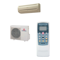
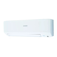
| Type | Split System |
| Power Supply | 220-240V, 50Hz |
| Rated Cooling Power Input | 1560 W |
Details the key features like remote control flap, auto operation, and self-diagnosis.
Explains the nomenclature used in model names for easy identification.
Describes how the unit indicates operational abnormalities through lamps.
Lists detailed technical specifications for different models, including capacity, power, and dimensions.
Defines the permissible operating conditions and limitations for the units.
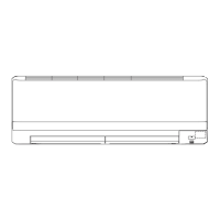
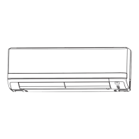
Provides detailed dimensional drawings for indoor and outdoor units.
Illustrates the refrigerant flow path and components within the system.
Guides on how to adjust cooling capacity based on temperature and piping length.
Details the electrical connections, color symbols, and component meanings.
Explains the functions and indicators of the wireless remote controller.
Describes manual switch operation and auto-restart feature after power loss.
Explains the different flap movement modes: AUTO, Swing, and Memory.
Details how the timer adjusts operation start time based on room temperature.
Describes the operation of indoor fan, flaps, and 52C during cooling.
Explains the operation blocks and cycles for dehumidifying modes.
Details how the unit determines the operation mode automatically.
Explains fan speed changes, auto fan control, and high power fan operation.
Covers dew condensation prevention, frost prevention, and self-diagnosis indicators.
Highlights critical safety measures and warnings for installation.
Provides recommendations for indoor and outdoor unit placement.
Step-by-step guide for mounting the indoor unit and related components.
Instructions for connecting wires and forming pipes for the indoor unit.
Covers outdoor unit placement, fixing, and connecting wiring.
Details steps for connecting refrigerant pipes, air purging, and charging.
Outlines the process for conducting a trial run and confirming operation.
Provides a flowchart for initial troubleshooting before PCB replacement.
Explains the meaning of flashing lamps for diagnosing indoor unit faults.
Details troubleshooting steps for outdoor unit, fan motor, and thermistor issues.
Presents diagnostic procedures for unit malfunctions and component checks.
Provides a chart for diagnosing issues related to temperature thermistors.