-
176
-
'20 • PAC-SM-351
Read these "Precauons for safety" carefully before starng disassembly work and do it in the proper way.
When disassembling, be sure to turn off the power. When disassembling the electrical components, check the electrical wiring diagram.
The electrical components are under high voltage by the operaon of the booster capacitor.
Fully discharge the capacitor before commencing a repair work. Failure to observe this warning could result in electric shock.
When parts of refrigerant cycle is disassembled by welding, be sure to work aer collecng a refrigerant, if the refrigerant isn't
collected, the unit might explode.
Be sure to collect refrigerant without spreading it in the air.
These contents are an example. Please refer to a similar part of actual unit.
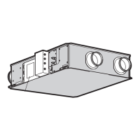
To remove the lid of control box
Remove 2 lid fixing screws and remove it.
To remove the printed circuit board (PCB)
Remove the lid of control box.(See No.1)
Pull off all the inserted connectors.
Take off 4 control PCB fixing locking supports(
Take off 6 power PCB fixing locking supports(
To remove the boom panel(B)
Remove 18 panel fixing screws and remove it.
To remove the impellers and motors(FM)
Remove the lid of control box.
Remove the lid of control box.(See No.1)
Remove the boom panel(B).(See No.3)
Remove the boom panel(B).
Disconnect the motor connector(CNFMx or CNMx) on PCB in control box.
Remove the motor fixing screw and remove it.
Disconnect the motor PCB connector
(CNFMx or CNMx)on PCB in control box.
Remove the fan casing fixing screw and remove it.(
Remove 2 motor PCB fixing screws
Remove the sirocco fan fixing bolt and remove it.(
To remove the temperature sensors (example"Thi-A")
Remove the lid of control box.(See No.1)
Remove the boom panel(B).(See No.3)
Disconnect the Thi-A connector(CNH) on PCB in control box.
Pull the temperature sensor fixing clip and remove it.(
(FDU FDUM series)
PJG012D019
Control PCB
Power PCB
Motor
Motor PCB
Motor
(Boom)
(Top)
Boom panel(B)
1
(c) FDU, FDUM series
PJG012D019

 Loading...