-
57
-
'20 • PAC-SM-351
a) Replace the control PCB
i) Unscrew terminal (Arrow A) of the "E1" wiring (yellow/green) that is connected to PCB.
ii) Replace the PCB only after all the wirings connected to the connector are removed.
iii) Fix the board such that it will not pinch any of the wires.
iv) Switch setting must be same setting as that of the removed PCB.
v) Reconnect the all wirngs to the PCB, that was removed in ii).
vi) Rescrew the terminal (Arrow A) of the "E1" wiring, that was removed in i).
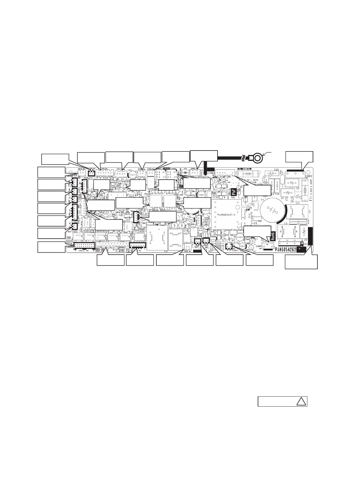
b) Control PCB (※Parts mounting are different by the kind of PCB.)
CNW3(White)
CNQ(Red)
CNR(White)
CNV2(Black
)
CNV(White)
CNH(Black)
CNTA(Blue)
CNL(Black)
CNC(White)
CNF(Yellow)
CNN(Yellow)
CNI(Blue)
CNJ1(White)
CNJ2(Grey) CNB(Black)
CNM1(White)
CNP(Green)
A
CNT(Blue)
CNG(Blue)
CNW0(White)
CNA (Red) CNK2(Black) CNK1(White)
Part number
CNT2(Red)
CNWR(White)
SW2
SW7
SW6
LED3
SW5
LED2
(Green)
(Red)
1) Model FDT series
D
PSC012D050
 Loading...