-
75
-
'20 • PAC-SM-351
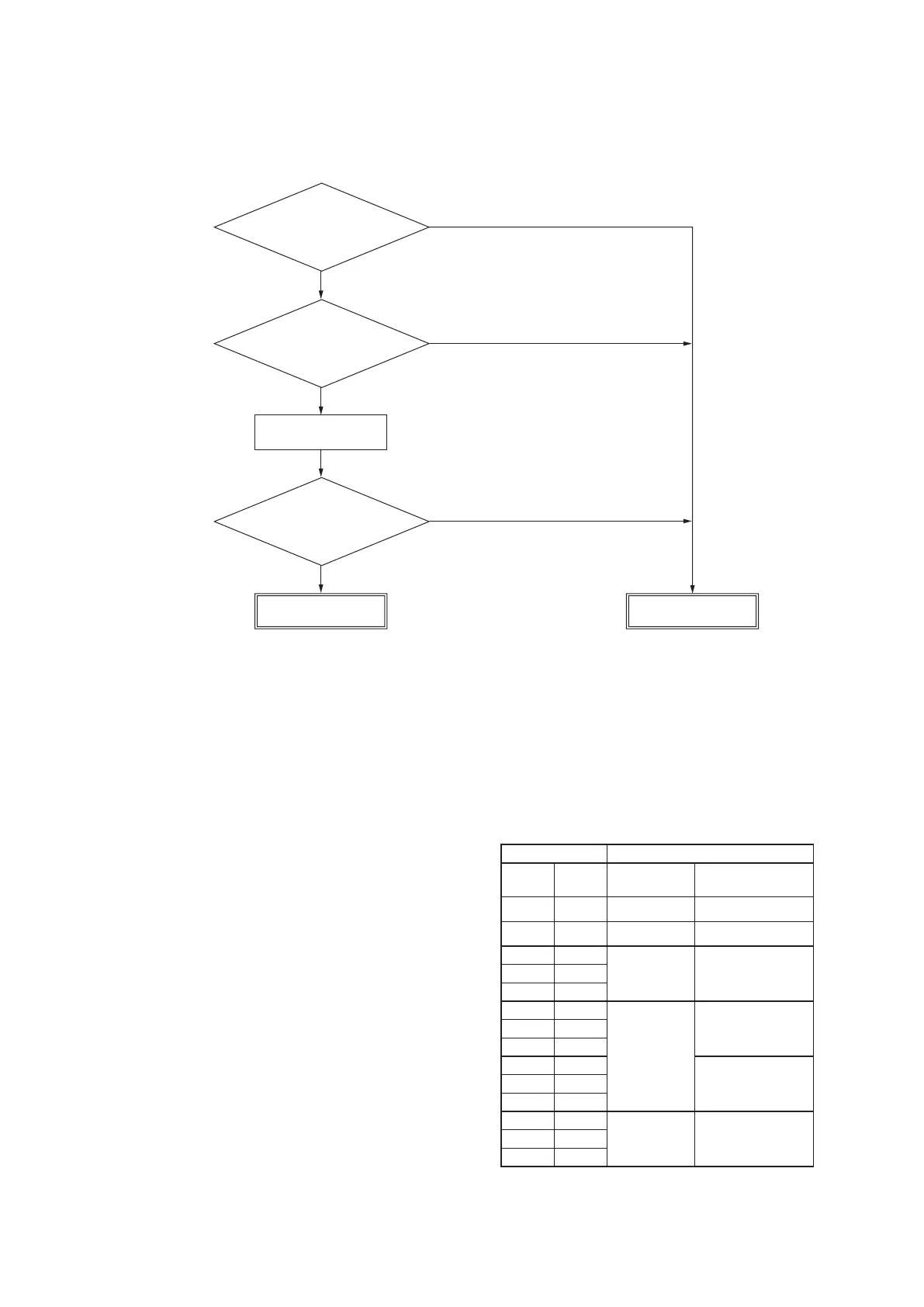
(6) Power transistor module (Including the driver PCB) inspection procedure
Compressor operation
Replace the outdoor
unit inverter PCB
Normal
YES
YES
YES
NO
NO
NO
Is the power
transistor module
cracked or burnt?
Is there a
short circuit between the
power transistor module
terminals?
∗
1
If there is a 10% or greater difference
in the current in different phases.
(except during acceleration or deceleration)
Is there any difference in
the compressor current
between phases?
*
1 Power transistor module terminal short circuit check procedure
Disconnect the compressor wiring, then conduct a short circuit check.
P-U, P-V, P-W
N-U, N-V, N-W
Check between the P-N terminals.
Bring the tester probes in contact with the following
places on each te rminal.
P: Power transistor P terminal
N: Power transistor N terminal
U: End of red harness to compressor
V: End of white harness to compressor
W: End of black or blue harness to compressor
Check for a power transistor short-circuit.
•
When you do not have a diagnostic checker for judging
if the inverter is defective, measure between the terminal
on the inverter PCB, judge whether the power transistor is
defective or not.
• Disconnect the compressor, then measure with the
control incorporated.
Models FDC100-140VNX-W, 100-140VSX-W
Tester Normal value (W)
Terminal
(+)
Terminal
(-)
FDC100-
140VNX-W
FDC100-
140VSX-W
P N Approx. 230 k Approx. 50 k
N P Approx. 570 k Approx. 525 k
P U
Approx. 420 k Approx. 260 kP V
P W
N U
Approx. 250 k
Approx. 215 kN V
N W
U P
Approx. 235 kV P
W P
U N
Approx. 480 k
Approx. 280 kV N
W N
If the measured values range from 0 - several kW, there is a possibility
that the elements are damaged, so replace the power transistor parts.
 Loading...