-
77
-
'20 • PAC-SM-351'20 • PAC-SM-351
t°
t°
t°
t°
t°
t°
t°
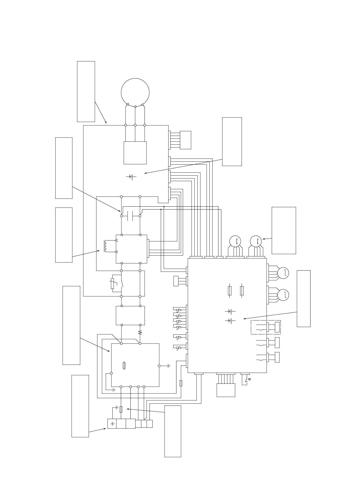
Models FDC100VNX, 125VNX, 140VNX
●
Outdoor unit check points
Check items with the *mark when the power is ON.
*
LED1
(Yellow)
LED2
(Red)
LED1
(Green)
Must be conductive.
When fuse is blown,
replace it or check wiring.
L1
TB
PCB3
DM
52X1
L1
C1
DIP-IPM
RAM
RAM
63H1
CM
A/F MODULE
INVERTER PCB
NOISE FILTER
PCB1
PCB2
CONTROL PCB
L1i
Red
Yellow/Green
Red
White
White
White
Blue
F 250V 30A
F 250V 4A
F 250V 8A
L1o
E1
CT1
TB1
TB2
TB10
TB11
~
~
-
+
-
N2
P
L2
P
N2
TB7
U
V
W
CNECNI4CNI2CNACT1
TB8
TB9
L1
+
E
Ni
1
2
No
N
1
2
3
CNA2CNPS
PSL
CNTHCNBCNIPCNW
CNW2
CNE
CNH
CNR CNS
CNEEV1 CNEEV2
CNFAN1
CNA1
CNI3
CNI1
18V
15V
FMO1
M
M
M
SM2SM1
20S
CNF
OPTION
DH
CH1
THo-R2
THo-P
THo-A
THo-S
THo-D
THo-R1
Power source check:
Measure the power source L1,N
(It is normal if it is AC220-240V)
Noise filter check:
There should be continuity.
There should be no shorts between phases.
DC Reactor continuity Check:
Max 25mΩ
Capacitor check:
Check for anomaly in appearance
such as damage, swelling, etc.
Check the power transistor
module if there is short, open, or
breakdown on the elements
LED1 (Yellow) Check :
Red
White
Blue
When the outdoor
unit fan motor is
abnormal:
(Refer to page 120•163)
LED2(Red) check:
1-5 time flash : Refer to page 53•54
F1 (250V, 2A)
F2 (250V, 4A)
CNFAN2
FMO2
M
1-7 time flash
(Refer to page 53•54)
Models FDC100VNX-W, 125VNX-W, 140VNX-W
(8) Outdoor unit control failure diagnosis circuit diagram
 Loading...