─ 9 ─
6. Circuit board diagrams
Circuit board diagrams and check points <FU-M05-D4>
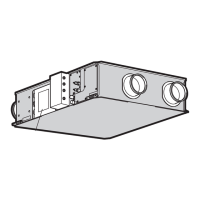
1 GUF-50RD4, GUF-50RDH4, GUF-100RD4, GUF-100RDH4
LEV
Power supply
220-240 V AC 50 Hz
14 V DC
12 V DC
5 V DC
GND
External humidifier
control input
Operation monitor output
ZKHQVWRSSHG
GXULQJRSHUDWLRQ
MA remote controller
transmission cable
M-NET
transmission cable
M-NET
transmission cable
6KLHOGHGSDUW
Error monitor output
QRUPDOO\
when there is an error
Supply fan
&RPPRQ
Fuse
$9 7UDQVIRUPHUSULPDU\LQSXW
7UDQVIRUPHUVHFRQGDU\RXWSXW
16 to 23 V AC
KLJK
low
OA thermistor
Damper motor
220-240 V AC 50 Hz
Limit switch
RA thermistor
Gas pipe thermistor
Water sensor
Liquid pipe thermistor
LED3
On when M-NET line
power is on.
LED1
On when power is on.
Exhaust fan
&RPPRQ
Supply fan
220-240 V AC
50 Hz
KLJK
low
Exhaust fan
220-240 V AC
50 Hz
Solenoid value
Full-wave rectified YROWDJH
of 220-240 V AC 50 Hz
(GUF-50/100RDH
4W\SHV
LED2
On when MA remote
controller power is on.
Address switch
7HQVGLJLW
Address switch
2QHVGLJLW
Branch No. switch
Function switch 3
Function switch 2
Function switch 1
 Loading...