TROUBLESHOOTING
ENGINE COOLING
14-11
TECHNICAL DESCRIPTION
• The fan controller has variable control of the cool-
ing fan motor speed using signals transmitted
from the engine-ECU.
TROUBLESHOOTING HINTS
• Malfunction of fan control relay
• Malfunction of fan controller
• Malfunction of engine-ECU
DIAGNOSIS
STEP 1. Check the fan control relay.
Refer to P.14-17.
Q: Is the fan control relay in good condition?
YES : Go to Step 2.
NO : Replace the part, then go to Step 8.
STEP 2. Check the harness wire between fan
control relay connector A-09X terminal 2 and fan
controller connector A-17 terminal 3.
AC310900
AB
Connector: A-09X
A-09X
3
1
4
2
Relay box
side
AC210859
Connector: A-17
A-17 (GR)
AD
Fan controller
Component side
Q: Are the harness wire between fan control relay
connector A-09X and fan controller connector A-17
damaged?
YES : Repair or replace the part, then go to Step
6
.
NO : Go to Step 3.
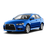
STEP 3. Measure the output circuit voltage at
engine-ECU connector C-121 terminal 18 by
backprobing.
AC505254
16
25
10
24
1
9
24
27
13
26
11
3
12
2829
1415
3031
1718
3332
6
20
5
19 21
35
34
8
23
7
22
JAE
AB
Connector: C-121 <LHD>
Harness side
C-121 (GR)
Engine-ECU
AC505255
16
25
10
24
1
9
24
27
13
26
11
3
12
2829
1415
3031
1718
3332
6
20
5
19 21
35
34
8
23
7
22
JAE
AB
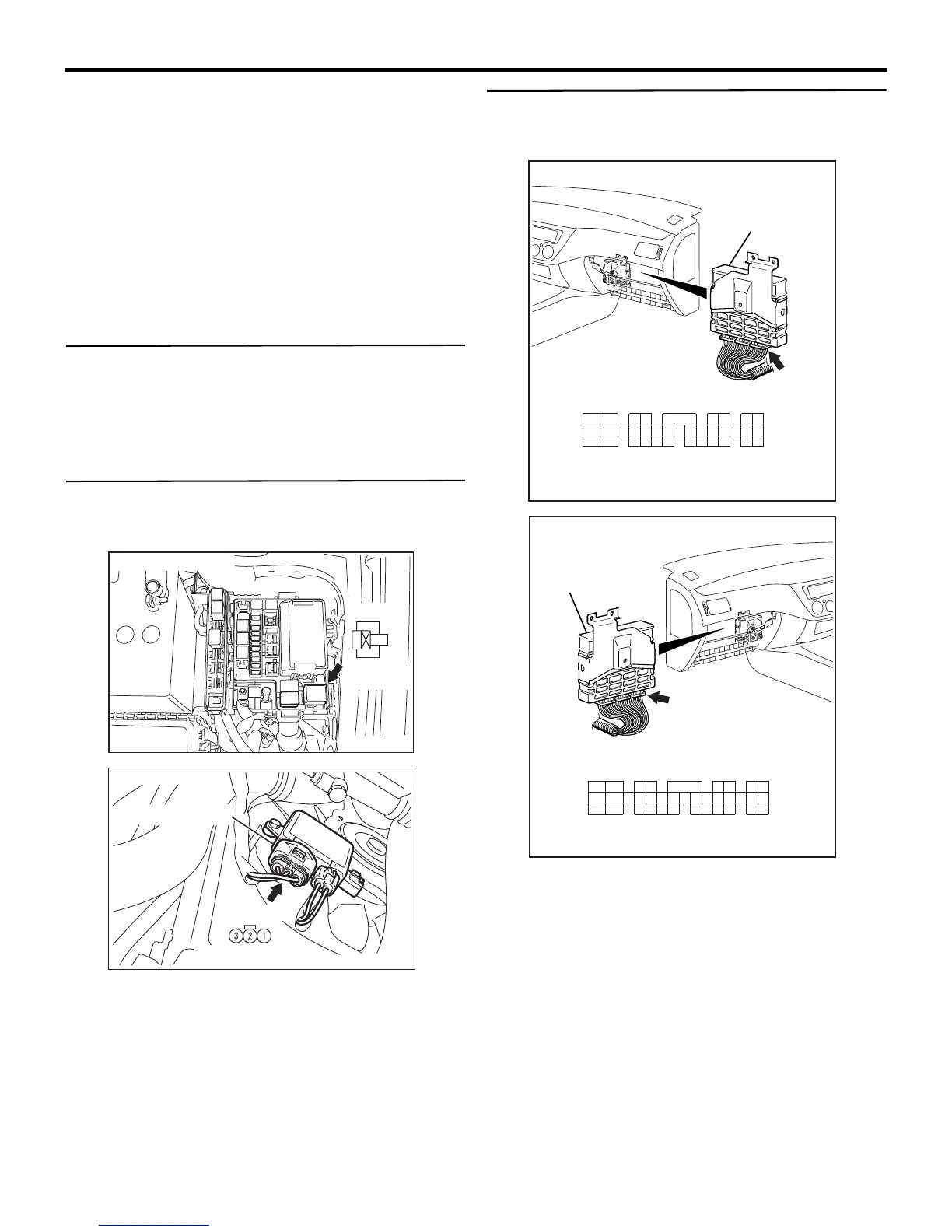
Connector: C-121 <RHD>
Harness side
C-121 (GR)
Engine-ECU
(1) Do not disconnect engine-ECU connector C-121.
(2) Start the engine and allow it to idle.
(3) Measure the voltage between terminal No.18 and
earth by backprobing.
• The voltage should measure less than 0.3 volt
when the cooling fan is not operating.
Q: Is the voltage less than 0.3 volt when the cooling
fan is not operating?
YES : Go to Step 6.
NO : Go to Step 4.
 Loading...