GENERAL - Supplemental Restraint System (SRS)
00-23
SRS-ECU
Terminal No.
Destination of harness Corrective action
7 Instrument panel wiring harness → Earth Repair or replace each wiring
8 Instrument panel wiring harness → Combination meter
(SRS warning lamp)
arness
9, 10 Instrument panel wiring harness → Front passenger’s air bag
module
11, 12 Instrument panel wiring harness → Clock spring → Driver’s air bag
module)
Repair or replace the dash wiring
harness. Replace clock spring.
13 Instrument panel wiring harness → Junction block (fuse No.3) Repair or replace each wiring
16 Instrument panel wiring harness → Junction block (fuse No.2)
arness.
20 Instrument panel wiring harness → Diagnosis connector
29, 30 Floor wiring harness → Driver’s seat belt pre-tensioner
27, 28 Floor wiring harness → Front passenger’s seat belt pre-tensioner
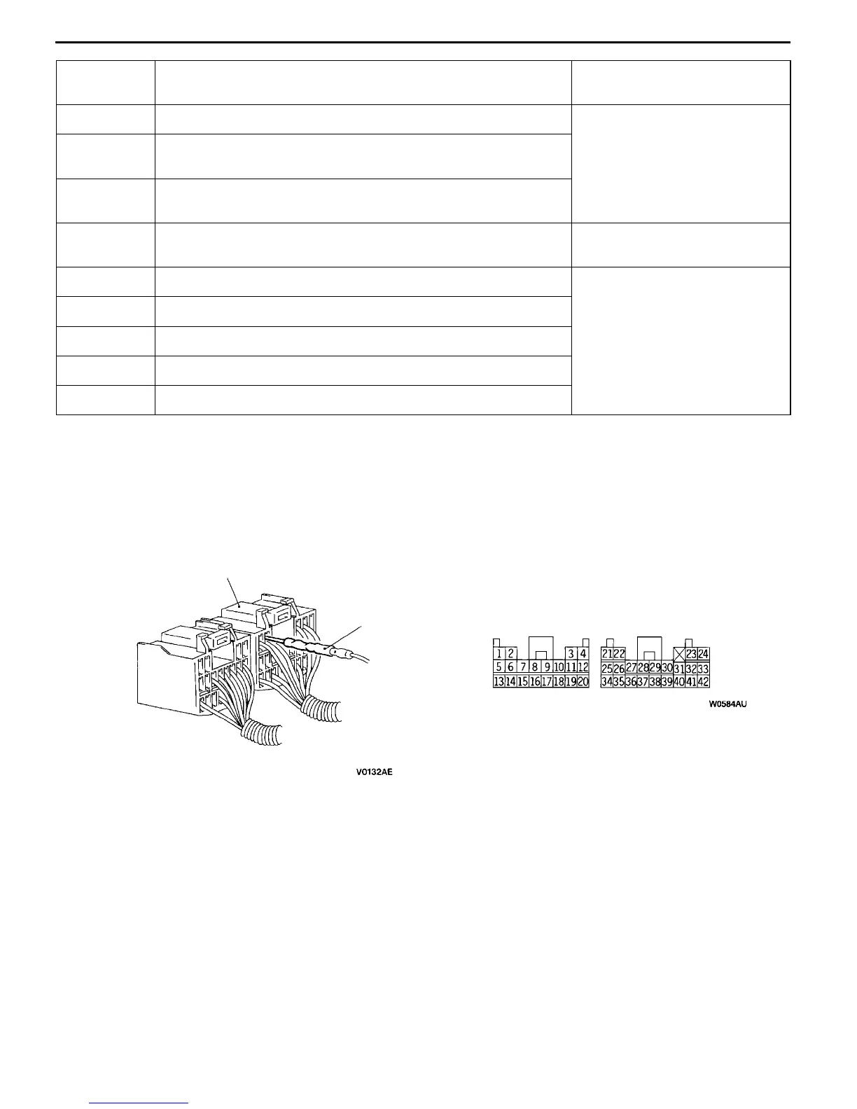
6. Inspection of the SRS-ECU harness connector should be carried out by the following procedure.
Insert the special tool (probe, MB991222, in the harness set) into the connector from harness side
(rear side), and connect the tester to this probe. If any tool than specified is used, damage to the
harness and other components will result. Furthermore, measurement should not be carried out by
touching the probe directly against the terminals from the front of the connector. The terminals are
plated to increase their conductivity, so that if they are touched directly by the probe, the plating
may break, which will cause drops in reliability.
MB991222
SRS-ECU harness connector
SRS-ECU harness connector (rear view)
7. SRS components and seat belt with pre-tensioner should not be subjected to hart, so remove the
SRS-ECU, driver’s and front passenger’s air bag modules, clock spring, and seat belt with pre-tensioner
before drying or baking the vehicle after painting.
D SRS- ECU, air bag module, clock spring : 93
℃
or more
D Seat belt with pre-tensioner : 90
℃
or more
8. Whenever you finish servicing the SRS, check warning lamp operation to make sure that the system
functions properly. (Refer to P.52B-6.)
9. Make certain that the ignition switch is LOCK (OFF) position when the MUT-II is connected or
disconnected.
10. If you have any questions about the SRS, please contact your local distributor.
NOTE
SERIOUS INJURY CAN RESULT FROM UNINTENDED AIR BAG DEPLOYMENT, SO USE ONLY
THE PROCEDURES AND EQUIPMENT SPECIFIED IN THIS MANUAL.

 Loading...