8
CN560
CN591
123456
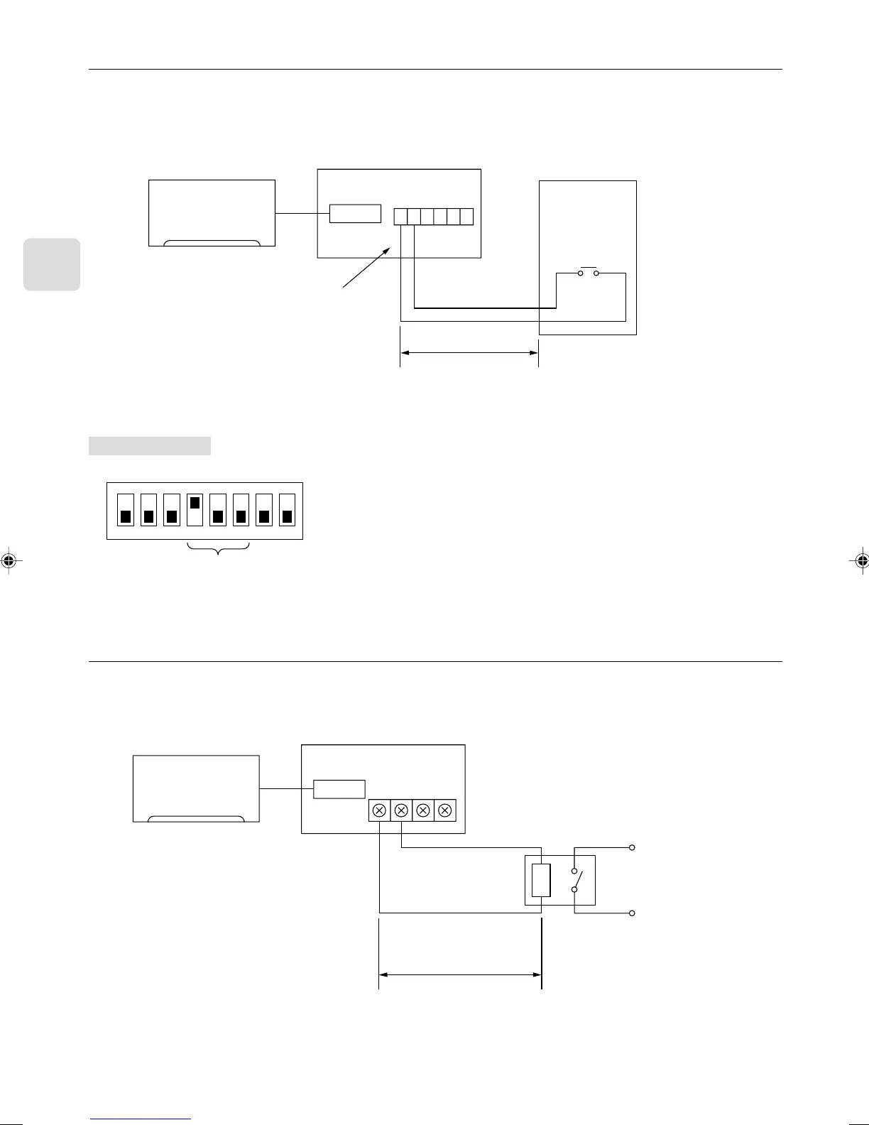
4.5. Status Signal Output Using the Relay
• You can set the external relay to ON/OFF based on whether the Indoor unit is set to either on/off or error/ok.
• Set up and wire the relay and extension cables at the installation site.
• Please use relays with reinforced insulation.
CN560
TB580
12AB
Indoor unit
Interface unit 1
Relay B
(coil rating of DC12 V 75 mA or less)
Dip switch settings
■ SW500
■ SW501 and SW502 do not have to be set.
ON
1
2 3 4 5 6 7 8
Setting required
100 m max.
Extend the cord using the exten-
sion cord A at the installation
site.
4.4. Restricting Indoor Unit Operations from the Contact Point
• You can use a coin timer or light switch to ensure that Indoor unit will not operate.
• Connect the supplied lead wires (6) E to the connector CN591 on the interface board.
• Wire the remote control components, including the coin timers or switches, at the installation site.
• Please use extension cords with reinforced insulation.
Indoor unit
Interface unit 1
Lead wires (6) E
Contact point a
(about 10 mA)
* When the contact point is open, the unit will turn off and will not be operable from the remote control.
When the contact point is closed, the unit will turn on and will be operable from the remote control.
Coin timer B
100 m max.
Extend the cord using
the extension cord A at
the installation site.
Brown
Red