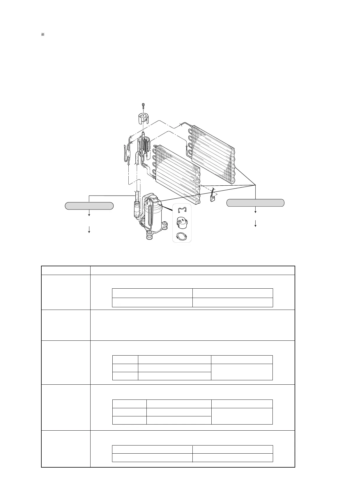
Noise increase
No humidifying
Gas leak from the cooler, condenser or discharge pipe.
Troubleshooting: Replace cooler or condenser; or replace
discharge pipe welding.
Pipe/pipe contact
Pipe/cabinet contact
Troubleshooting: Repair pipe molding
If the customer complains that the unit won’t dehumidify, make the following checks before starting to repair the
coolant circuit:
1 Clogged filter, or dust: ➞ Action: Clean.
2 Low-temperature, low-humidity operating environment:
➞ Action: See the explanation of the graph on page 9, or move the unit to a kitchen or bathroom and
request verification of its performance.
★ If the problem persists, check the cooler tube temperature.
Normal: At least 10°C lower than the room temperature ➞ If not lower than the room temperature by 10°C or
more, repair the coolant circuit.
7.3 Key Component Check Procedures
Component name
Testing procedure
Tub temperature
sensing thermistor
Room
temperature and
humidity sensor
board
Compressor
Fan motor
Solenoid valve
coil
Detach the connector and measure the resistance using a multimeter
(component temperature: 10°C to 30°C).
Detach the connector and measure the resistance using a multimeter
(component temperature: 10°C to 30°C).
With the connector detached, measure the resistance across the terminals using a multimeter
(winding temperature: 10°C to 30°C).
Normal
Abnormal
Between P11 pins: 8.0kΩ to 20.8kΩ
Normal: 47 to 51kΩ (between P10 pins 3 and 4)
Abnormal: Open or shorted
P11
Open or shorted
Normal
Abnormal
Open or shorted
Measure the resistance between terminals using a multimeter
(component temperature: 10°C to 30°C).
Measure the resistance between terminals using a multimeter
(winding temperature: 10°C to 30°C).
2.6kΩ ~ 2.9kΩ
Open or shorted
Normal
Abnormal
25.0Ω ~ 27.1Ω
67.9Ω ~ 73.5Ω
C-R side
C-S side
Open or shorted
Normal
Abnormal
258Ω ~ 280Ω
379Ω ~ 411Ω
Yellow-Blue
Black-Blue
 Loading...