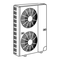
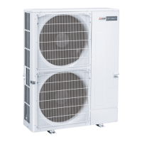
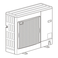
TECHNICAL & SERVICE MANUAL
SPLIT-TYPE, AIR CONDITIONERS
CONTENTS
1. FEATURES ························································2
2. TECHNICAL CHANGE······································3
3.
COMBINATION OF INDOOR AND OUTDOOR UNITS
··············4
4. PART NAMES AND FUNCTIONS·····················4
5. SPECIFICATIONS ·············································5
6. DATA··································································6
7. OUTLINES AND DIMENSIONS ························9
8. WIRING DIAGRAM··········································13
9.
REFRIGERANT SYSTEM DIAGRAM
···················18
10. MICROPROCESSOR CONTROL····················19
11. TROUBLESHOOTING ·····································21
12. DISASSEMBLY INSTRUCTIONS····················25
13. PARTS LIST·····················································29
<Outdoor unit>
Models
Outdoor unit
PU12EK
PU18EK PU18EK
1
PU24EK PU24EK1 PU24EK2 PU24EK3
PU30EK PU30EK1 PU30EK2 PU30EK3
PU36EK PU36EK1 PU36EK2 PU36EK3
PU42EK2 PU42EK21
PU42EK7 PU42EK71 PU42EK72
No. OC247
REVISED EDITION-E
•Please void OC247 REVISED EDITION-D.
Revision:
•Wiring diagram for PU12EK has been modified in
”8. WIRING DIAGRAM”.
•Transformer and outdoor controller board for
PU12EK has been modified in ”13. PARTS LIST”.
Note:
•Refer to other manual as for Indoor Units.
Model name
indication
OC247-E--1.qxp 04.8.11 4:25 PM Page 1


 Loading...