APPENDICES
Appendix 2 Special Register List
App - 88
9
Parameters
10
Device Explanation
11
CPU Module Processing
Time
12
Procedure for Writing
Program to CPU ModuleAppendicesIndex
(17)For redundant systems (Host system CPU information
*1
)
SD1510 to SD1599 are only valid for redundant systems.
They are all set to 0 for stand-alone systems.
*1: The information of the host CPU module is stored.
TableApp.35 Special register
Number Name Meaning Explanation
Set by
(When Set)
Corres-
ponding
ACPU
D9
Corresponding
CPU
SD1512
Operation mode
during CPU
module start up
Hot start switch
power out time
• Shows the power out time (S) during the automatic switch from hot start
to initial start in the operation mode when the CPU module is started up.
S (Initial) New Q4AR
SD1585
Redundant
system LED
status
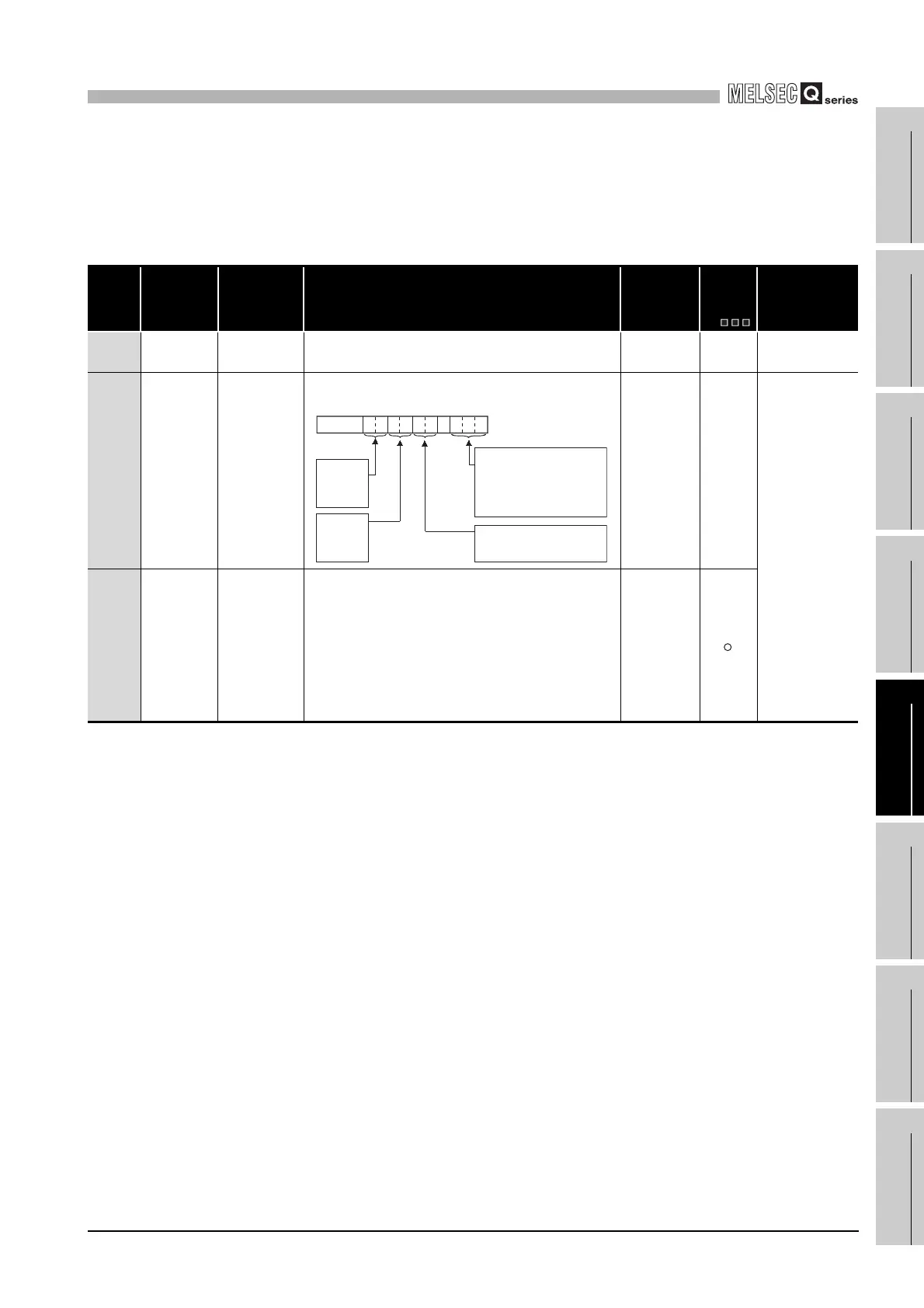
4 LED states
• BACKUP
• CONTROL
• SYSTEM A
• SYSTEM B
The LED status for BACKUP, CONTROL, SYSTEM A, SYSTEM B is
stored in the following format:
S (status
change)
New
QnPRH
SD1588
Reason(s) for
system
switching
Reason(s) for
system switching
that occurred in
host station
Stores the reason(s) for system switching on the host system.
The following values are stored corresponding to the methods for system
switching:
Initialized to 0 when the power supply is switched off and then on or the
RESET switch is set to the RESET position and then to the neutral
position.
0: Initial value (control system has not been switched)
1: Power off, Reset, H/W failure, WDT error,
2: CPU stop error (except WDT)
3: System switching request from network module
16: System switching dedicated instruction
17: System switching request from GX Developer
S (when
condition occurs)
b0tob2b3b4b5b6b7b8b10b9b15
00
to
SYSTEM B
0: Off
1: On
2: Flicker
SYSTEM A
0: Off
1: On
2: Flicker
CONTROL
0: Off
1: On
BACKUP
0: Off
1: On (red)
2:
3: On(green)
4: Flicker(green)
Flicker(red)
5: On (orange-yellow)
6: Flicker
(orange-yellow)
 Loading...