App - 89
Appendix 2 Special Register List
APPENDICES
TableApp.35 Special register
Number Name Meaning Explanation
Set by
(When Set)
Corres-
ponding
ACPU
D9
Corresponding
CPU
SD1589
Reason(s) for
system
switching failure
conditions
Reason(s) for
system switching
failure No.
• Stores the reason(s) for system switching failure.
0: System switching normal (default)
1: Tracking cable is not connected , tracking cable error, FPGA circuit
failure.
2: H/W failure, power-OFF, Reset, WDT error on the standby system
3: H/W failure, power-OFF, Reset, WDT error on the Control system
4: Tracking data transfer initialization
5: Communication timeout
6: Serious error(except WDT error) on the Standby system
7: There is difference between both systems
(detected as Backup mode only)
8: During memory copy from control system to standby system
9: During online program change
10: During detection of intelligent function module failure on the standby
system
11: System switching being executed
• Resets to "0" when host system is powered on.
• Resets to "0" once system has been switched successfully.
S(when system
is switched)
QnPRH
SD1590
Switch request
network No.
Request source
network No.
• Stores the request source at work No. when the SM1590 is turned on. S (Error) New Q4AR
Network module
head address,
which requested
system
switching
Network module
head address,
which requested
system switching
• Stores head address of network module which a system switch request
was initiated.
• Turns off automatically by system, after network error is reset by user.
• Please refer to SD1690 which stores the corresponding head address of
network module on other system.
S (Error/Status
change)
New
QnPRH
SD1595
Memory copy
target I/O
number
Memory copy
target I/O number
• Stores the memory copy target I/O No.(Standby system CPU module:
3D1H) of before SM1595 is turned from OFF to ON.
UNew
SD1596
Memory copy
status
Memory copy
status
• Stores the execution result of Memory copy function.
0 : Memory copy successfully completed
4241
H : Standby system power supply off
4242
H : Tracking cable is disconnected or is damaged
4247H : Memory copy function is being executed
4248H : Unsupported memory copy destination I/O Number
S (Status
change)
New
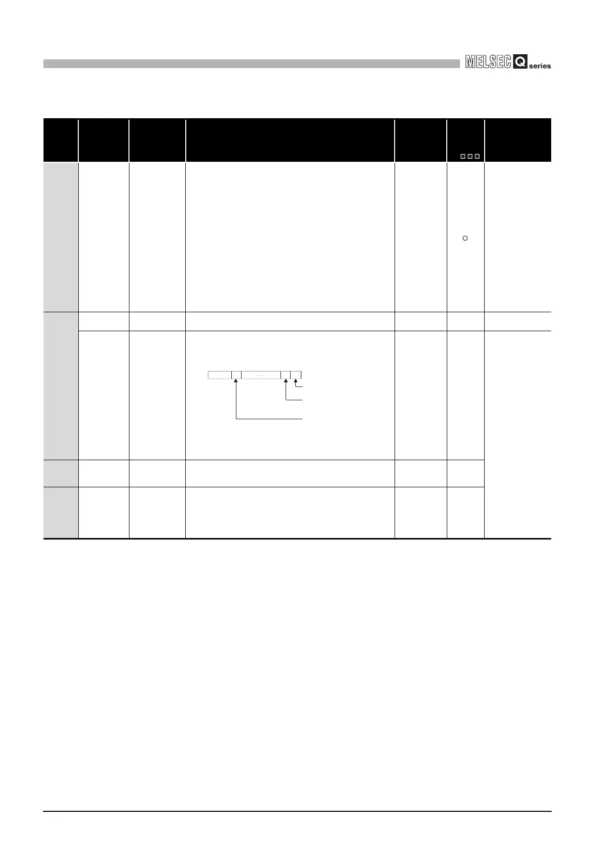
b1 b0b15 b11to to
0
0/1
0/1 0
Module 0:
Module 1:
Module11:
SD1590
Each bit
0:OFF
1:ON
to
CPU module is invalid
as it is 2-slot model.
Module on the right
side of the CPU module
Module at the
rightmost end of the
12-slot base (Q312B)
 Loading...