APPENDICES
Appendix 2 Special Register List
App - 92
9
Parameters
10
Device Explanation
11
CPU Module Processing
Time
12
Procedure for Writing
Program to CPU ModuleAppendicesIndex
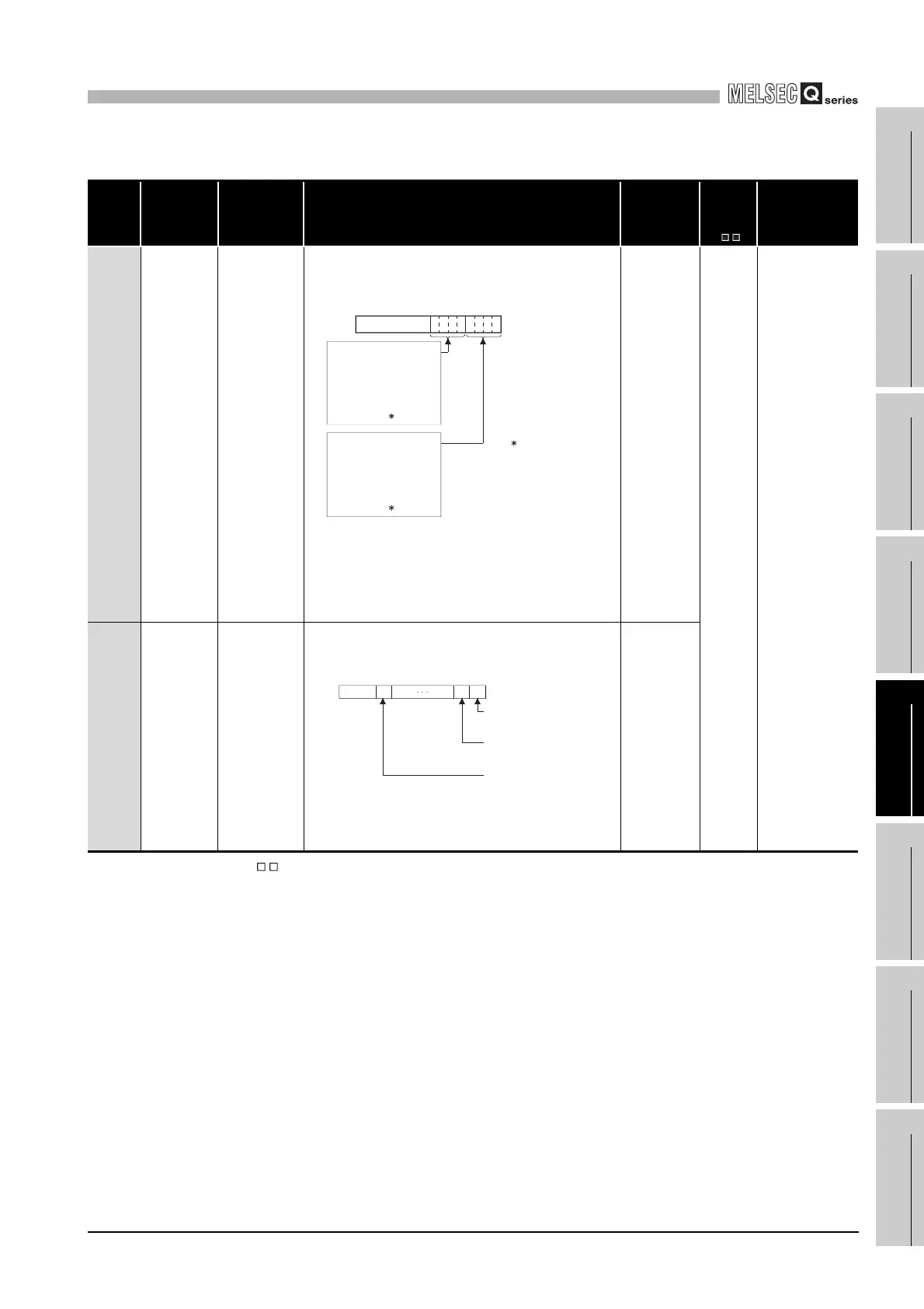
*2 : Shows the special register (SD ) for the host system CPU.
TableApp.36 Special register
Number Name Meaning Explanation
Set by
(When Set)
Corres-
ponding
ACPU
SD *2
Corresponding
CPU
SD1650
Other system
operating
information
Other system
operating
information
Stores the operation information of the other system CPU module in the
following format.
"00FFH" I stored when a communication error occurs, or when in debug
mode.
Note : A communication error is caused by the following:.
• When the power supply is switched off, or when the other system is
reset.
• H/W error occurs on either of system A or B.
• WDT error occurs.
• Tracking cable is not connected.
• Tracking cable is disconnected or damaged.
S(Every END)
–QnPRH
SD1690
Network module
head address,
which requested
system
switching on
host (control)
system
Network module
head address,
which requested
system switching
on host (control)
system
• Stores head address of network module which a system switch request
was initiated, using the following format.
• Turns off automatically by system, after network error is reset by user.
• Please refer to SD1590 which stores the corresponding head address of
network module on host system.
S(Every END)
0:No error
1:Continue error
2:Stop error
F:Communication with
other system
disabled
0:RUN
2:STOP
3:PAUSE
F:Communication with
other system
disabled
: Communication
with other system
disabled, debug
mode
b15 to tob8 b4b7 tob3 b0
0
SD1650
)
(
)
(
to
b1 b0
b15 b11to to
0
0/1
0/1 0
Module 0: CPU module is
invalid as it is 2-
slot model
Module 1: Module on the
right side of the
CPU module
Module11: Module at the
rightmost end of
the 12-slot base
(Q312B)
SD1690
Each bit
0:OFF
1:ON
 Loading...