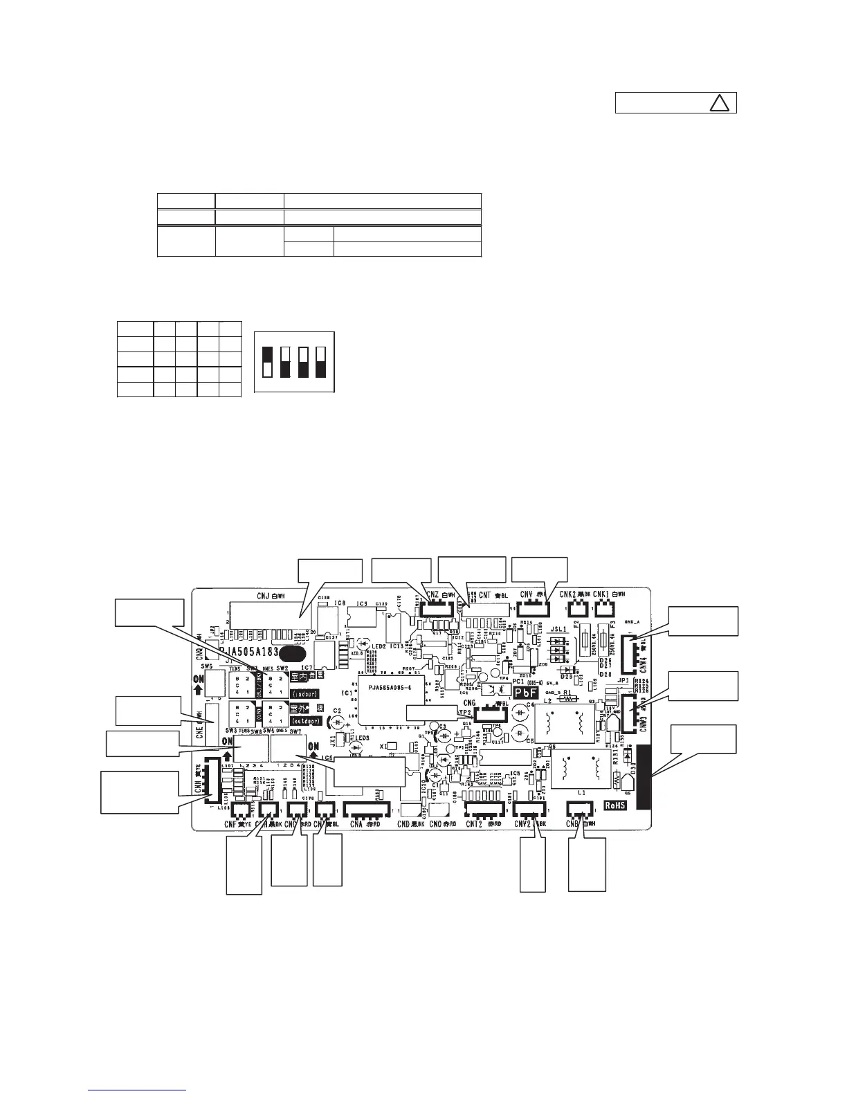
Replace and set up the PCB according to this instruction.
① Set to an appropriate address and function using switch on PCB.
Select the same setting with the removed PCB.
② Set to an appropriate capacity using the model selector switch(SW6).
Select the same capacity with the PCB removed from the unit.
③ Replace the PCB
1. Fix the PCB so as not to pitch the cords.
2. Connect connectors to the PCB. Connect a cable connector with the PCB connector of the same color.
3. Do not pass CPU surrounding about wirings.
④ Control PCB
Parts mounting are different by the kind of PCB.
〇:ON -:OFF
Part number
SW2 (Blue)
Address setting
 Loading...