EasyManua.ls Logo

Mitsubishi SEZ-A12AR User Manual

Mitsubishi SEZ-A12AR
24 pages
To Next Page IconTo Next Page
Page #1 background imageLoading...
Page #1 background image
TECHNICAL & SERVICE MANUAL
CONTENTS
1. PART NAMES AND FUNCTIONS········3
2. SPECIFICATIONS·································5
3. OUTLINES AND DIMENSIONS············8
4. WIRING DIAGRAM·······························9
5.
REFRIGERANT SYSTEM DIAGRAM
······10
6. TROUBLESHOOTING························11
7. DISASSEMBLY PROCEDURE···········18
8. PARTS LIST········································21
9. OPTIONAL PARTS·····························23
INDOOR UNIT
Indoor unit
[Model names] [Service Ref.]
SEZ-A12AR SEZ-A12AR.TH
SEZ-A18AR SEZ-A18AR.TH
SEZ-A24AR SEZ-A24AR.TH
SPLIT-TYPE, HEAT PUMP AIR CONDITIONERS
WIRED REMOTE
CONTROLLER
ON/OFF
CENTRALLY CONTROLLED
ERROR CODE
CLOCK
ON OFF
˚C
CHECK
CHECK MODE
FILTER
TEST RUN
FUNCTION
˚C
1Hr.
NOT AVAILABLE
STAND BY
DEFROST
TEMP.
Ceiling Concealed
Series SEZ
R410A
Model name
indication
Note :
•This manual does not cover the
following outdoor units. When
servicing them, please refer to
the service manual No.OC304
REVISED EDITION-A and this
manual in a set.
Please void OC303.
Revision :
•“ 2. SPECIFICATIONS ” has
been modified.
No.OC303
REVISED EDITION-A
OC303-A-1.qxp 04.9.21 4:08 PM Page 1
Question and Answer IconNeed help?

Do you have a question about the Mitsubishi SEZ-A12AR and is the answer not in the manual?

Mitsubishi SEZ-A12AR Specifications

General IconGeneral
BrandMitsubishi
ModelSEZ-A12AR
CategoryAir Conditioner
LanguageEnglish

Summary

PART NAMES AND FUNCTIONS

Operation Buttons Overview

Describes the function and operation of various buttons on the wired remote controller for different modes.

Display Indicators

Explains the various display symbols, icons, and indicators shown on the wired remote controller.

SPECIFICATIONS

Electrical Parts Specifications

Details the specifications and rating conditions for main electrical components of the indoor unit.

NOISE CRITERION CURVES

OUTLINES AND DIMENSIONS

WIRING DIAGRAM

REFRIGERANT SYSTEM DIAGRAM

TROUBLESHOOTING

Troubleshooting Cautions and Self-Check Procedures

Outlines safety precautions and steps for initiating the unit's self-diagnosis function.

Trouble Codes and Symptoms

Lists specific error codes and their corresponding operational symptoms for easy diagnosis.

Troubleshooting Specific Issues

Details causes and countermeasures for common operational problems and error codes.

Main Part Test Points and Criteria

Provides guidance on testing key internal components and their resistance criteria for normal operation.

DISASSEMBLY PROCEDURE

PARTS LIST

Structural Parts

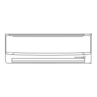
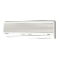
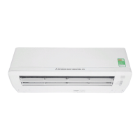
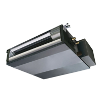
Lists the part numbers and names for the structural components of the indoor unit.

Electrical Parts

Lists the part numbers and names for the electrical components of the indoor unit.

OPTIONAL PARTS

Refrigerant Extension Pipes

Details the specifications and models for optional refrigerant extension pipes.

Air Filters

Lists the applicable air filter models for the specified indoor units.

Related product manuals