Do you have a question about the Mitsubishi SKM40ZA and is the answer not in the manual?
Details long piping, connectable capacity, and unit types for multi-split systems.
Explains the coding used in product model names for identification.
Lists capacities, noise levels, dimensions, and other specs for SKM22ZA, 25ZA, 28ZA indoor units.
Details specifications for the SRRM40ZA ceiling recessed indoor unit.
Lists specifications for the SCM80ZA outdoor unit.
Defines operating conditions, limits, and restrictions for the SCM80ZA outdoor unit.
Provides detailed dimensional drawings for SKM22ZA, 25ZA, and 28ZA indoor units.
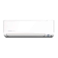
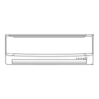
Provides detailed dimensional drawings for SKM32ZA, 40ZA, and 50ZA indoor units.
Provides detailed dimensional drawings for the SRRM40ZA ceiling recessed indoor unit.
Provides detailed dimensional drawings and installation space requirements for the SCM80ZA outdoor unit.
Illustrates the refrigerant piping layout for the SCM80ZA model, showing component connections.
Provides methods to correct cooling/heating capacity based on temperature and piping length.
Shows the wiring connections for SKM22ZA, 25ZA, 28ZA, 32ZA, 40ZA indoor units.
Details wiring diagrams for SKM50ZA and SRRM40ZA indoor units.
Provides the electrical wiring diagram for the SCM80ZA outdoor unit.
Details the functions of buttons, indicators, and modes on the remote controller.
Describes the meaning of RUN and TIMER lamps on indoor units for different models.
Explains how to use the back-up switch for unit operation and detail of operation.
Describes the AUTO flap operation for cooling, dry, and heating modes across different indoor unit types.
Explains memory flap function and swing flap movement for wall-mounted and ceiling-recessed units.
Details how the comfort timer adjusts next operation start time based on temperature.
Explains the pleasant reservation timer for SRRM models, its conditions, and function.
Overview of capacity control and outdoor unit frequency control for cooling.
Overview of capacity control and frequency control for heating.
Describes hot keep operation for preventing cool wind blow during heating.
Details the conditions that trigger the defrosting operation in normal and accelerated modes.
Explains how to determine and set cooling/heating modes using the remote control.
Details compressor start control, soft start, and protection mechanisms.
Explains controls to return oil to the compressor at low outdoor frequencies.
Explains controls to protect the compressor at high outdoor frequencies.
Describes abnormal stop conditions due to low current or improper operation.
Details conditions and actions for compressor overheat protection, including frequency control.
Lists critical warnings and cautions for safe and proper installation work.
Covers installation cautions and mounting procedures for SKM series indoor units.
Details the process of mounting and connecting indoor/outdoor interconnecting wires for SKM and SKM50 models.
Provides instructions on shaping pipes and drain hoses, and drainage considerations.
Explains how to securely mount the indoor unit to the installation board.
Covers cautions and installation procedures for SRRM ceiling recessed indoor units.
Details mounting method of batteries and fixing the remote controller to a pillar or wall.
Covers selection of installation location and methods for installing the outdoor unit.
Provides guidelines for selecting an appropriate installation location for the outdoor unit.
Explains how to set the volt select switch on the control board based on voltage area.
Details the electrical wiring connections for the outdoor unit, including power lines.
Specifies recommended power supply wires and precautions for interconnection wiring.
Instructions for connecting crossover wires and pipes between indoor and outdoor units.
Details refrigerant pipe limits, diameters, and connection procedures.
Specifies maximum permissible refrigerant pipe lengths and height differences.
Provides step-by-step instructions for connecting refrigerant pipes, including tightening torques.
Explains when and how to add refrigerant based on pipe length.
Covers inspection, test run procedures, and customer explanation for proper operation.
Lists items to check after installation before turning on the power.
Details how to perform the test run and what to check for proper operation.
Lists and shows examples of optional parts for ceiling recessed installations.
Details the installation procedure and parts list for the RFD12 air outlet duct.
Details the installation procedure and parts list for the RKB12 air outlet grille.
Details the installation procedure and parts list for the RTS12 bottom air inlet grille.
Details the installation of the air outlet unit for ceilings using flexible ducts.
Details the specifications and parts provided for flexible ducts.
Details the installation procedure and parts list for the RFJ22 duct joint.
Details the installation procedure and components for the RDU12E drain up kit.
Outlines a flowchart for troubleshooting before deciding to replace the printed circuit board.
Explains error codes indicated by indoor and outdoor unit lamps and their causes.
Provides inspection steps for thermistor errors and current cut issues.
Details inspection procedures for outdoor unit errors, over current, and power transistor overheat.
Provides inspection steps for serial signal, fan motor, and drain errors.
Describes phenomena observed after thermistor shortcircuits or wire breakages.
Provides a flowchart for checking remote controller functionality and main unit operability.
Flowchart for inspecting indoor electrical components like fuses, transformers, and PCBs.
Details a diagnostic procedure to identify inverter defects and required replacements.
Highlights key points for inspecting inverter components like capacitors, diodes, and transistors.
Explains the process of purging impurities from the refrigerant system using a vacuum pump.
Details the steps for charging refrigerant into the system, including purging and weighing.
| Heating Capacity | 5.0 kW |
|---|---|
| Energy Efficiency Ratio (EER) | 3.21 |
| Power Supply | 220-240V, 50Hz |
| Refrigerant | R410A |
| Power Source | 220-240V, 50Hz |
| Cooling Capacity | 4000 W |
| Type | Split System |