1-49
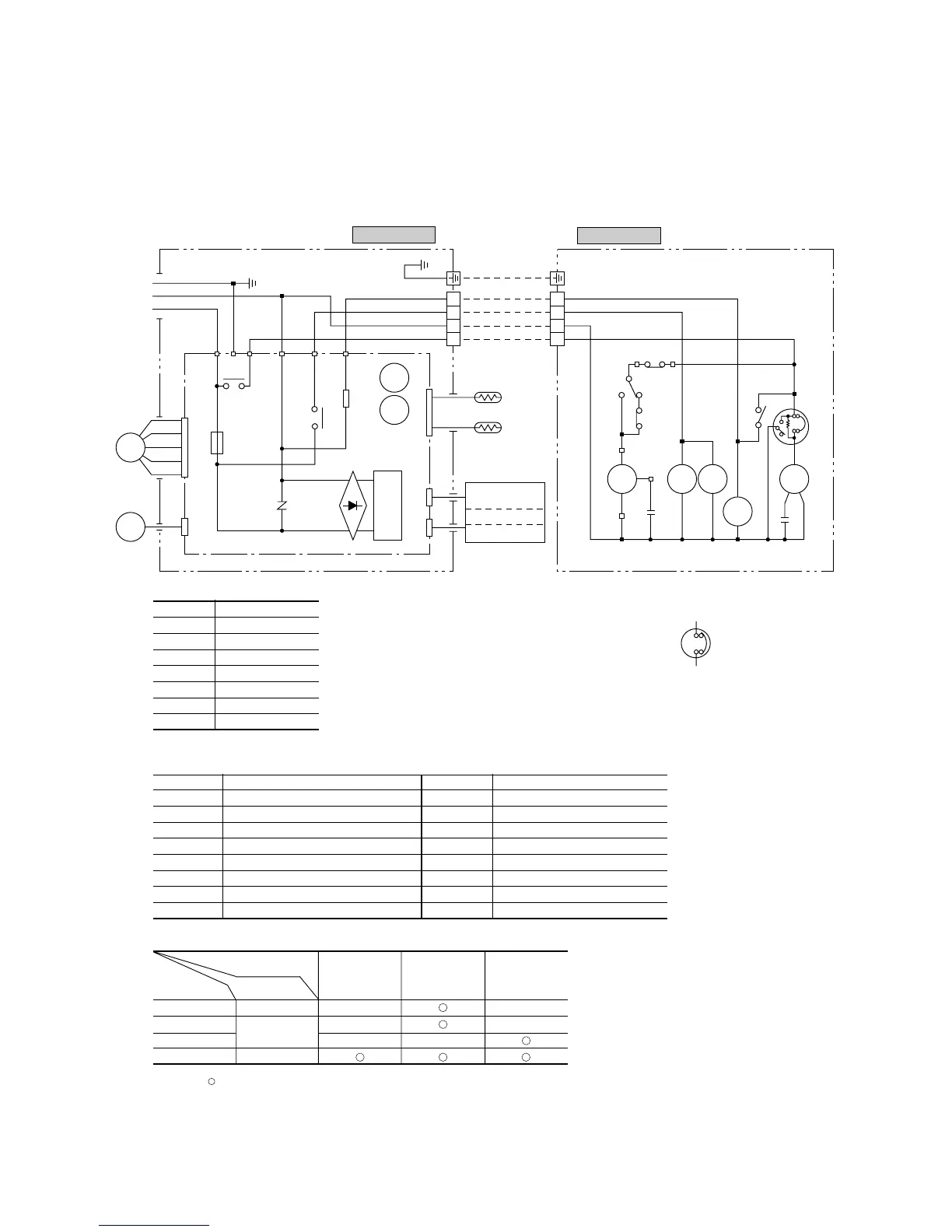
Notes (1) ; denotes magentized relay ×: denotes demagnetized relay
(2) Th
1
is room temperature thermistor. Th
2
(the heat exchanger thermistor) is the hot start, hot keep, and frost prevention thermistor.
(for details, refer to pages 19, 20, 22)
(3) Preset values :
23DH (defroster stop thermostat) : opens at over 14˚C
63H (overload protection high pressure switch during heating) : closes at 1.86(19.0 )/ opens at 2.41(24.5) [MPa(kgf/cm
2
)]
Meaning of marks
Symbol Parts name Symbol Parts name
C
C
Capacitor for CM Th
1, 2
Thermistor
CF
O
Capacitor for FM
O
ZNR Varistor
CM Compressor motor 20S 4 way valve. coil
F Fuse 51C Motor protector for CM
FM
I
Fan motor (Indoor unit) 52C Magnetic contactor for CM
FM
O
Fan motor (Outdoor unit) 52X
A, B, 1
Auxiliary relay
LM Louver motor 63H High pressure switch
PC Photo coupler 23DH Thermostat (Defrost)
Table of relay operations
Operation
Cooling Heating Defrost
Relay symbol Control part
52X
1
20S ××
52X
A
FM
O
××
52X
B
××
52C CM
Color symbol
BK Black
BL Blue
BR Brown
RD Red
OR Orange
WH White
Y Yellow
Y/GN Yellow/Green
Models SRK50HA, 56HA
Note(1) This figure shows SRK56HA. As for
SRK50HA, 51C differs as shown in the fig-
ure below.
51C
FM
I
LM
Y
BL
WH
BK
RD
5
4
3
2
1
CNU
F
250V
3.15A
ZNR
Printed circuit board
Power source
1 Phase 220/230/240V 50Hz
CNM
Y/GN
Y/GN
G
BL
BR
52C-4 52C-3 S 20S
52X1
52C
52X
1
PC
CNGCNHCNE
23D
52C
RD
OR
WH
BK
BL
RD
WH
BK
TH
1
TH2
1
2
3
4
1
2
RD 63H
52X
B
52XA
RD
WH
WHWH
BK
BK
WH
RD
RD
RD
RD
RD
BL
Cc
BL
BK
BK
BK
23
DH
51C
WH
BK
BK
BK
BK
OROR
CF0
20S
OR
ORRD
3
4
52X
B
CM
52X
A
( )
Indoor unit
Outdoor unit
Wireless
R-Amp
Display
Back up sw
FM0
 Loading...